7 connecting extvtg, See section 7.5.7 "connecting – SMA SI 3.0-11 Installation User Manual
Page 57
SMA Solar Technology AG
7 Electrical Connection
Installation Manual
SI30M-44M-60H-80H-IA-en-30
57
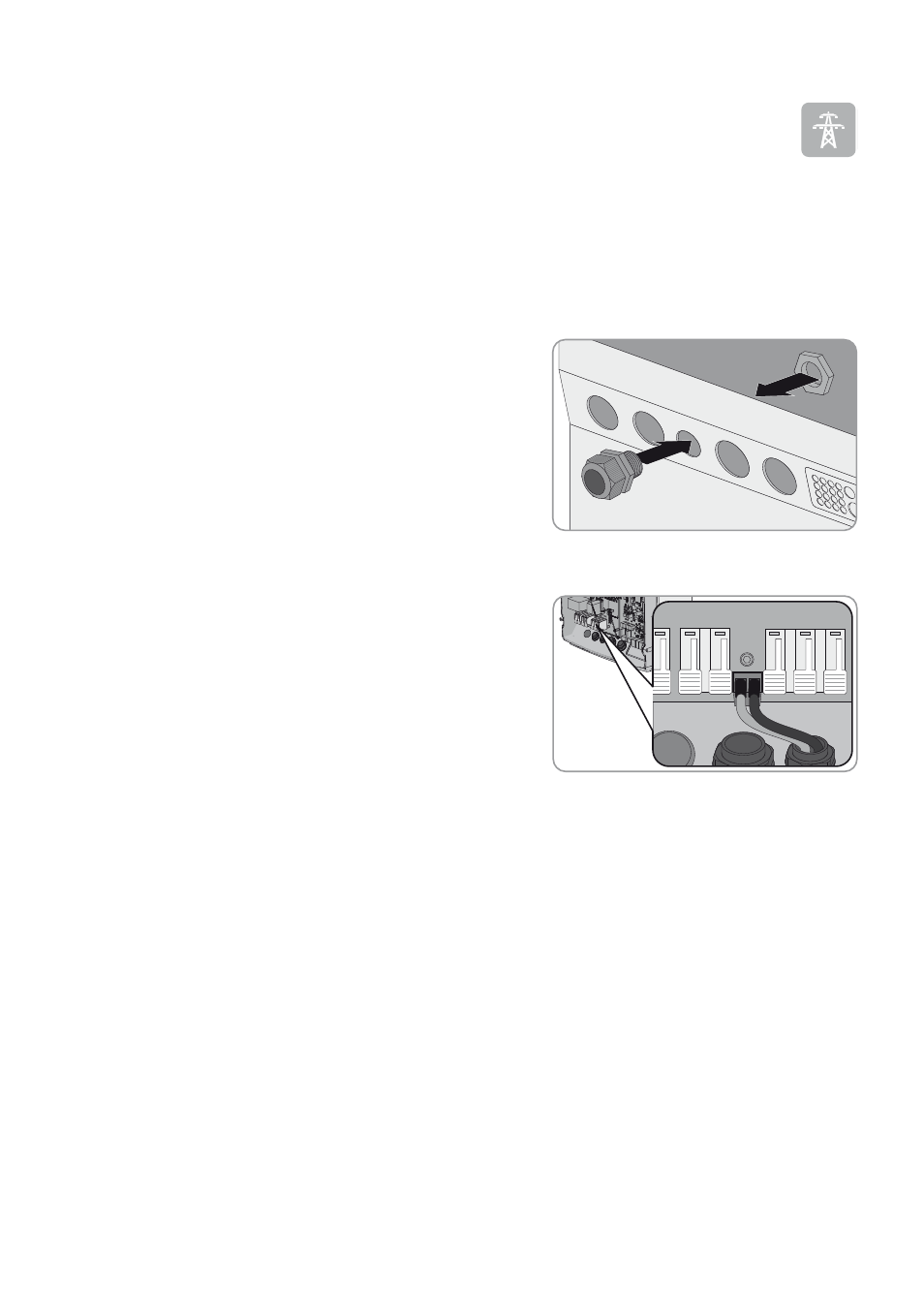
7.5.7 Connecting ExtVtg
Always connect the cable to the ExtVtg connection as follows.
Additionally required material (not included in the scope of delivery):
☐ Suitable bootlace ferrules if using stranded wire
Cable requirements:
☐ Copper wire
☐ Conductor cross-section: 0.2 mm² to 2.5 mm²
Procedure:
1. On the Sunny Island, attach the M20 cable gland to the PE/
ExtVtg enclosure opening with the counter nut (torque: 5 Nm).
2. Strip the cable insulation.
3. For stranded wires: press the bootlace ferrules onto the insulated conductors.
4. Lead the cable through the cable gland into the Sunny Island.
5. Connect the insulated conductors to terminal ExtVtg using the
2-pole terminal (torque: 0.5 Nm to 0.6 Nm) (for circuitry
overview, see the Quick Reference Guide "SMA Flexible Storage
System")
• Connect the line conductor to terminal ExtVtg L.
• Connect the neutral conductor to terminal ExtVtg N.
6. Tighten the swivel nut of the cable gland (torque: 2.6 Nm).