12 connecting load-shedding contactors, Ction 7.4.12) – SMA SI 3.0-11 Installation User Manual
Page 43
SMA Solar Technology AG
7 Electrical Connection
Installation Manual
SI30M-44M-60H-80H-IA-en-30
43
7.4.12 Connecting Load-Shedding Contactors
Load shedding prevents the battery deep discharge and controls the power output to the loads. Load shedding
provides the option of disconnecting specific loads from the system.
Load shedding is necessary for an off-grid system that is exclusively supplied with PV energy or wind energy.
The Sunny Island controls up to two load-shedding contactors depending on the state of charge of the battery. You can
install two types of load shedding:
• One-level load shedding
If the battery state-of-charge limit has been reached, one load-shedding contactor disconnects all loads at the same
time. Depending on the configuration, the load-shedding contactor closes when the battery has been sufficiently
charged or when the stand-alone grid has been switched to an external energy source.
• Two-level load shedding
In two-level load shedding, there are two thresholds for the state of charge of the battery in order to control two
load-shedding contactors. When the first threshold for the state of charge of the battery is reached, the first
load-shedding contactor disconnects a group of loads. When the second threshold for the state of charge of the
battery is reached, the second load-shedding contactor disconnects the remaining loads.
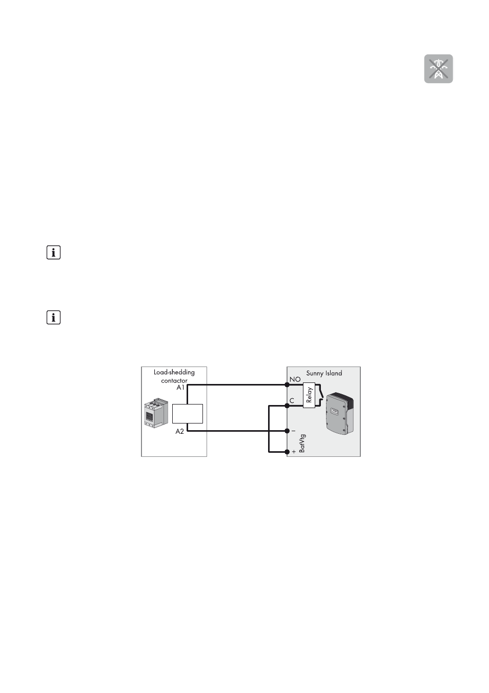
Figure 17: Connection of the control cable for one-level load shedding (example)
Requirements:
☐ The technical requirements of the multifunction relay must be met (see Section 10 "Technical Data", page 94).
Cable requirements:
☐ Copper wire
☐ Conductor cross-section: 0.2 mm² to 2.5 mm²
Procedure:
1. Ensure that the load-shedding contactor only disconnects loads from the system. This ensures that the battery can be
recharged from AC sources in the system.
2. Connect the insulated conductor for coil connection A1 of the load-shedding contactor to terminal Relay1 NO
(see Section 7.5.5 "Connecting Relay 1 and Relay 2", page 55).
Load shedding in a multicluster system
One-level load shedding is integrated into the Multicluster Box. The load-shedding contactor is controlled directly by
the master of the main cluster via communication with the Multicluster Box. If you install an additional load-shedding
contactor in a multicluster system, it is controlled with a multifunction relay in the master of extension cluster 1.
Additional load-shedding contactors cannot be controlled by the main cluster.
Load-shedding contactors in a cluster
If you connect load-shedding contactors to the master, limited operation is possible in the event of a disturbance.
Slaves can control the load-shedding contactors less reliably in the event of a fault. In the event of a disturbance,
the slave may wait for confirmation from the master.