Ction 7.4.13) – SMA SI 3.0-11 Installation User Manual
Page 44
7 Electrical Connection
SMA Solar Technology AG
44
SI30M-44M-60H-80H-IA-en-30
Installation Manual
3. Connect the insulated conductor for coil connection A2 to terminal BatVtgOut − (see Section 7.5.6 "Connecting
BatVtgOut, DigIn, BatTMP, and BatCur", page 56).
4. Connect terminal BatVtgOut + to terminal Relay1 C. Use the same conductor cross-section as that of the cable for
the load-shedding contactor.
5. Go to Section 8.1.5, page 66 and enter the following values in the table for configuration 1.
6. Repeat steps 1 to 5 for two-level load shedding. Connect the second load-shedding contactor to an unused
multifunction relay.
7.4.13 Connecting the Time Control for External Processes
The Sunny Island has two timers for time-dependent control of external processes. For each timer, you can set the starting
day and time that the multifunction relay is to be switched once, daily or weekly.
Requirements:
☐ The technical requirements of the multifunction relay must be met (see Section 10 "Technical Data", page 94).
Cable requirements:
☐ Copper wire
☐ Conductor cross-section: 0.2 mm² to 2.5 mm²
Procedure:
2. Go to Section 8.1.5, page 66 and enter the value TM1 for timer 1 or the value TM2 for timer 2 in the table for
configuration.
Value
Explanation
AutoLodExt
Setting for one-level load shedding. When the Sunny Island switches to an external energy
source, load shedding is stopped and the loads are supplied by the external energy source. The
battery is only charged with the excess energy.
AutoLod1Soc
Setting for one-level load shedding or the first level of two-level load shedding. Load shedding
is only stopped when the battery has been sufficiently charged.
AutoLod2Soc
Setting for the second level of two-level load shedding. Load shedding is only stopped when the
battery has been sufficiently charged.
MccAutoLod
Setting for additional one-level load shedding in a multicluster system. Load shedding is only
stopped when the batteries of the extension cluster have been sufficiently charged.
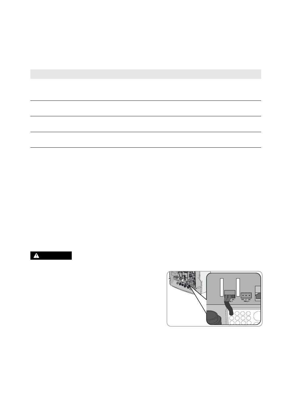
1.
:$51,1*
Danger to life from electric shock due to incorrect insulation
• Connect the control cable on the Sunny Island to either
multifunction relay Relay1 or Relay2 (see Section 7.5.5
"Connecting Relay 1 and Relay 2", page 55). Use the C and
NO terminals.