SMA SI 3.0-11 Installation User Manual
Page 59
SMA Solar Technology AG
7 Electrical Connection
Installation Manual
SI30M-44M-60H-80H-IA-en-30
59
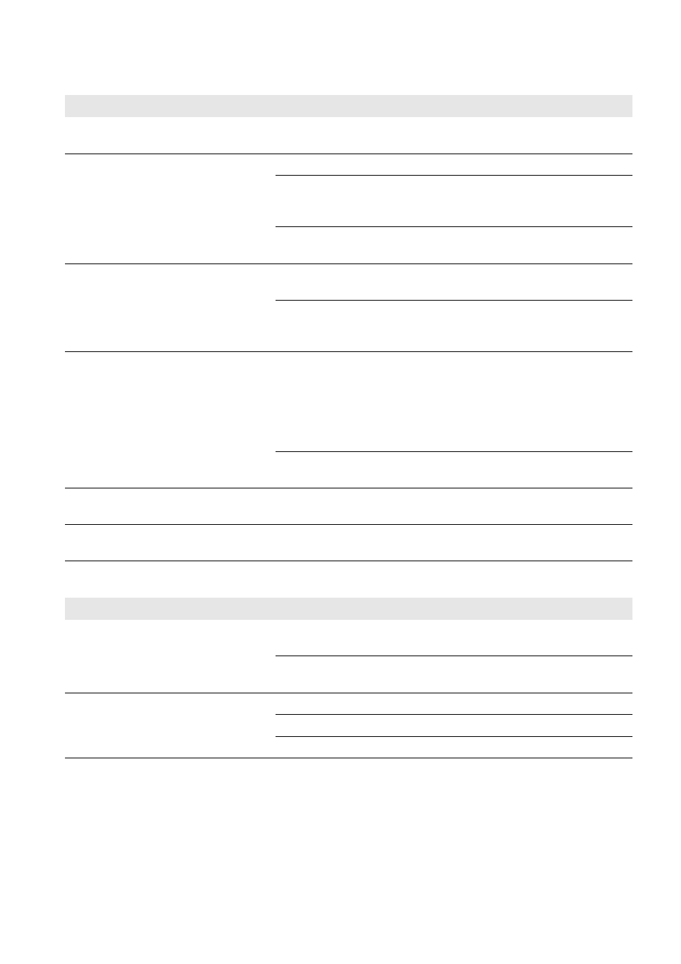
Checking the DC connection of the Sunny Island inverter
Checking connections AC1 and AC2 of the Sunny Island inverter
Test point
Test criterion
OK
Enclosure opening for DC
In the cable gland M32, the diameter of the DC power cable must
be 14 mm to 25 mm.
□
DC connection
Terminal lugs are pressed on firmly.
□
The bolted connection for fitting terminal lugs to the DC connection
is assembled as follows: head of M8x20 screw | spring washer |
fender washer | terminal lug | DC connection.
□
Terminal lugs are firmly fastened on the Sunny Island
(torque: 12 Nm).
□
DC power cable
The maximum length of cables from the battery via the BatFuse to
the Sunny Island is 10 m.
□
The conductor cross-section meets the cable requirements of
50 mm² to 95 mm² (for the recommended conductor cross-section,
see Section 7.4.1).
□
BatFuse
Fuse links are matched to the Sunny Island.
• SI3.0M-11: 80 A
• SI4.4M-11: 100 A
• SI6.0H-11: 160 A
• SI8.0H-11: 200 A
□
The cables are attached to the BatFuse with the required torque
(see BatFuse installation manual).
□
If installed, charge controllers and DC
loads
All charge controllers and DC loads are installed in accordance
with the manufacturer's specifications.
□
If installed, battery current sensor
The battery current sensor can be loaded with the maximum DC
current (see technical data of the battery current sensor).
□
Test point
Test criterion
OK
Enclosure openings AC1 and AC2
All enclosure openings are sealed with M25 cable glands or filler
plugs.
□
For an M25 cable gland, the cable diameter must be 9 mm to
18 mm.
□
Connections AC1 and AC2
All contact areas are not insulated.
□
All terminal levers are in the downward position.
□
All cables are securely clamped.
□