3 connecting the grounding conductor – SMA SI 3.0-11 Installation User Manual
Page 53
SMA Solar Technology AG
7 Electrical Connection
Installation Manual
SI30M-44M-60H-80H-IA-en-30
53
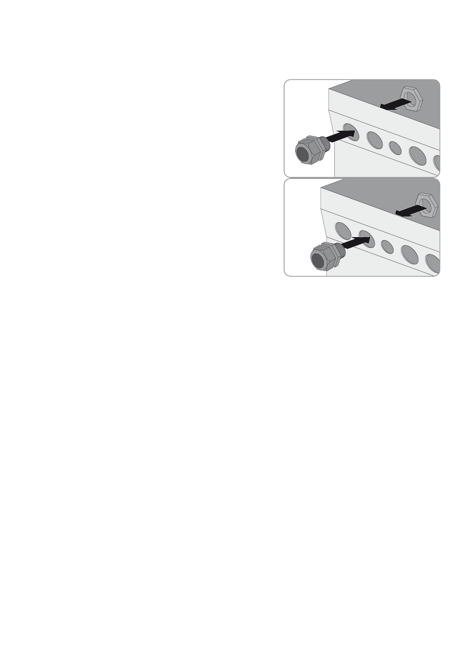
Procedure:
1. Push the levers of the AC1 or AC2 terminal upward.
2. When connecting the cable to connection AC1, attach the M25
cable gland to the AC1 enclosure opening using the counter nut
(torque: 7 Nm).
3. When connecting the cable to connection AC2, attach the M25
cable gland to the AC2 enclosure opening using the counter nut
(torque: 7 Nm).
4. Remove the cable jacket and strip the wire insulation by 13 mm.
5. Lead the cable through the cable gland into the Sunny Island.
6. Connect the insulated conductors to the terminals AC1 Loads/SunnyBoys or AC2 Gen/Grid.
• Insert the neutral conductor as far as it will go into terminal N or N
TT
and push the lever down.
• Insert the line conductor as far as it will go into terminal L and push the lever down.
• Insert the grounding conductor as far as it will go into terminal PE and push the lever down.
7. Tighten the swivel nut of the cable gland (torque: 4 Nm).
7.5.3 Connecting the Grounding Conductor
The Sunny Island must be connected to the ground potential via a grounding conductor on connection AC1 or AC2.
The conductor cross-section of the grounding conductor must be at least 10 mm². If the conductor cross-section is smaller,
an additional grounding conductor must connect the Sunny Island with the ground potential.
Additional grounding is fulfilled if the Sunny Island is already grounded due to the grounded battery (see Section 7.3
"Connecting the Grounding Conductor in Systems With Grounded Battery", page 25).
Cable requirements:
☐ Conductor cross-section:
– Cross-section of the connected line conductor or larger
– Maximum 16 mm²
☐ Cable diameter: 7 mm to 14 mm