5 format of g1_xist1 and g1_xist2, Figure 12 absolute value in g1_xist1, Figure 13 absolute value in g1_xist2 – HEIDENHAIN PROFIBUS-DP (DPV2) User Manual
Page 43: Format of g1_xist1 and g1_xist2, Figure 12, Absolute value in g1_xist1, Figure 13, Absolute value in g1_xist2
PROFIBUS IO data description
43
5.5 Format of G1_XIST1 and G1_XIST2
The G1_XIST1 and G1_XIST2 signals consist of the absolute
position value in binary format. By default the G1_XIST 1 signal is
equal to the G1_XIST2 signal. The format of the actual position
values in G1_XIST1 and G1_XIST2 is shown below.
Format definition for G1_XIST1 and G1_XIST2:
• All values are presented in binary format
• The shift factor is always zero (right aligned value) for both
G1_XIST1 and G1_XIST2.
• The setting in the encoder parameter data affects the position
value in both G1_XIST1 and G1_XIST2.
• G1_XIST2 displays the error message instead of the position
value if an error occurs. See also chapter 6.4 Error Message.
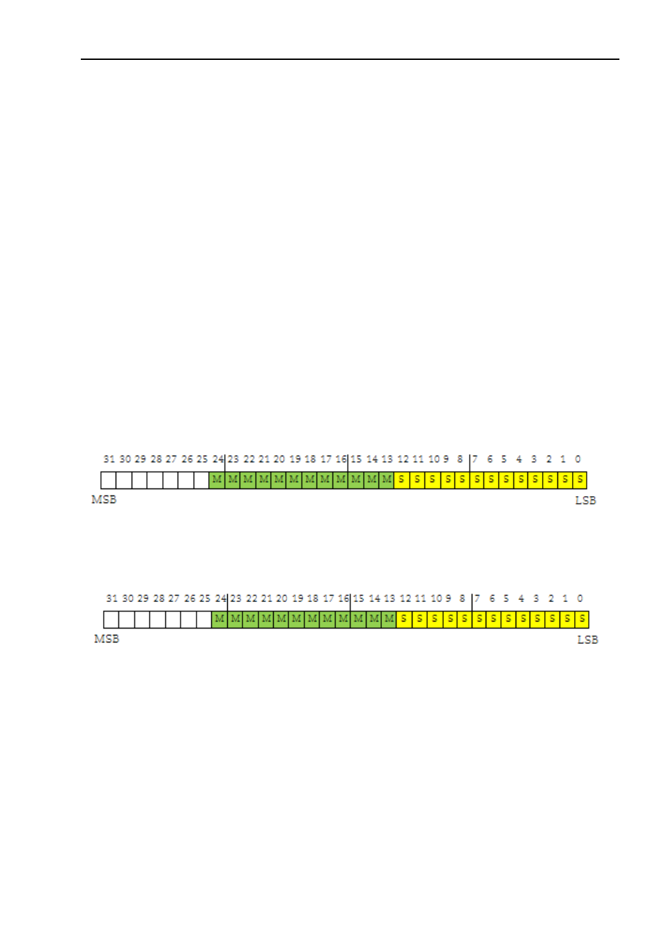
Example:
25 bit multi turn absolute encoder with gateway (8192
steps per revolution, 4096 distinguishable revolutions)
M = Multi turn value (Distinguishable revolutions)
S = Single turn value (number of steps per revolutions)
Figure 12
Absolute value in G1_XIST1
Figure 13
Absolute value in G1_XIST2