3 bus lines, Figure 5 orientation of m12 bus connectors, Bus lines – HEIDENHAIN PROFIBUS-DP (DPV2) User Manual
Page 16: Table 3, Pinning m12 bus in/out connectors, Figure 5, Orientation of m12 bus connectors
Encoder gateway installation
16
2.3 BUS lines
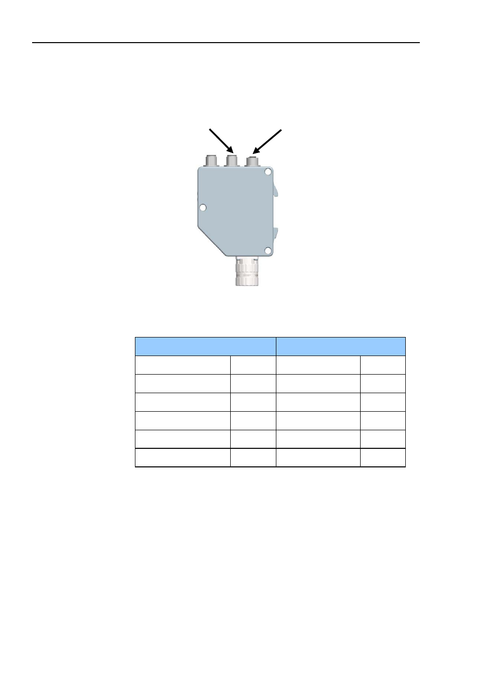
The PROFIBUS bus line connections of the M12 equipped
devices are constituted by a male B-coded 5 pin M12 connector
(bus in), and a female B-coded 5 pin M12 connector (bus out).
Figure 5
Orientation of M12 bus connectors
Bus in line
Bus out line
Function
Pin
Function
Pin
Not connected
1
VP
1
A
2
A
2
Not connected
3
DGND
3
B
4
B
4
Chassis
5
Chassis
5
Table 3
Pinning M12 bus in/out connectors
Bus in
Bus out
See also other documents in the category HEIDENHAIN Equipment:
- TNC 122 User Manual (63 pages)
- TNC 122 Technical Manual (70 pages)
- TNC 360 Service Manual (157 pages)
- TNC 416 Technical Manual (510 pages)
- TNC 335 Technical Manual (581 pages)
- TNC 360 User Manual (237 pages)
- TNC 360 ISO-Programmierung (2 pages)
- TNC 415 (280 540) User Manual (227 pages)
- TNC 370D (92 pages)
- TNC 416 (289 pages)
- TNC 415 (280 540) Technical Manual (752 pages)
- TNC 415 (259 96x) Service Manual (195 pages)
- TNC 407 (280 580) User Manual (376 pages)
- iTNC 530 (340 420) Pilot (104 pages)
- TNC 407 (280 580) ISO Programming (333 pages)
- TNC 415 (280 540) Service Manual (252 pages)
- PT 880 Installation (112 pages)
- ND 100 User Manual (116 pages)
- ND 287 User Manual (147 pages)
- ND 280 Quick Start (12 pages)
- ND 200 (156 pages)
- ND 282 (10 pages)
- ND 287 Quick Start (26 pages)
- ND 282 B (39 pages)
- ND 281 A (44 pages)
- ND 281 B v.1 (53 pages)
- ND 281 B v.2 (65 pages)
- ND 221 v.2 (10 pages)
- ND 231 B v.2 (56 pages)
- ND 231 B v.1 (44 pages)
- ND 221 B v.2 (45 pages)
- ND 550 v.2 (8 pages)
- NDP 560 (10 pages)
- ND 523 (93 pages)
- ND 570 (8 pages)
- ND 750 v.2 (46 pages)
- ND 760 v.3 (72 pages)
- ND 770 v.1 (40 pages)
- ND 770 v.3 (41 pages)
- ND 760 E (44 pages)
- IOB 49 (21 pages)
- NDP 960 (68 pages)
- ND 780 Installation (132 pages)
- ND 970 (47 pages)
- ND 1100 Quick Start (36 pages)