Figure 4, Terminal connections of power supply cables – HEIDENHAIN PROFIBUS-DP (DPV2) User Manual
Page 15
Encoder gateway installation
15
Encoder gateways equipped with cable glands are delivered with
a dust protection foil from the factory. The protection foil needs to
be removed prior to installing the cables.
It is recommended that gateways equipped with cable glands are
equipped with a shielded power supply cable with conductor area
between 0,34 mm
2
to 1.5 mm
2
. Permissible outer cable diameter
is ø 6 mm to ø 8 mm for the power supply cable. The power
supply screw terminal is located inside the back cover of the
gateway.
In the case were the gateway is the last node in the bus-structure
and only the cable glands for Supply and Bus-in is in use, the Bus
out cable gland should be replaced with a M16 filler plug to
ensure proper sealing.
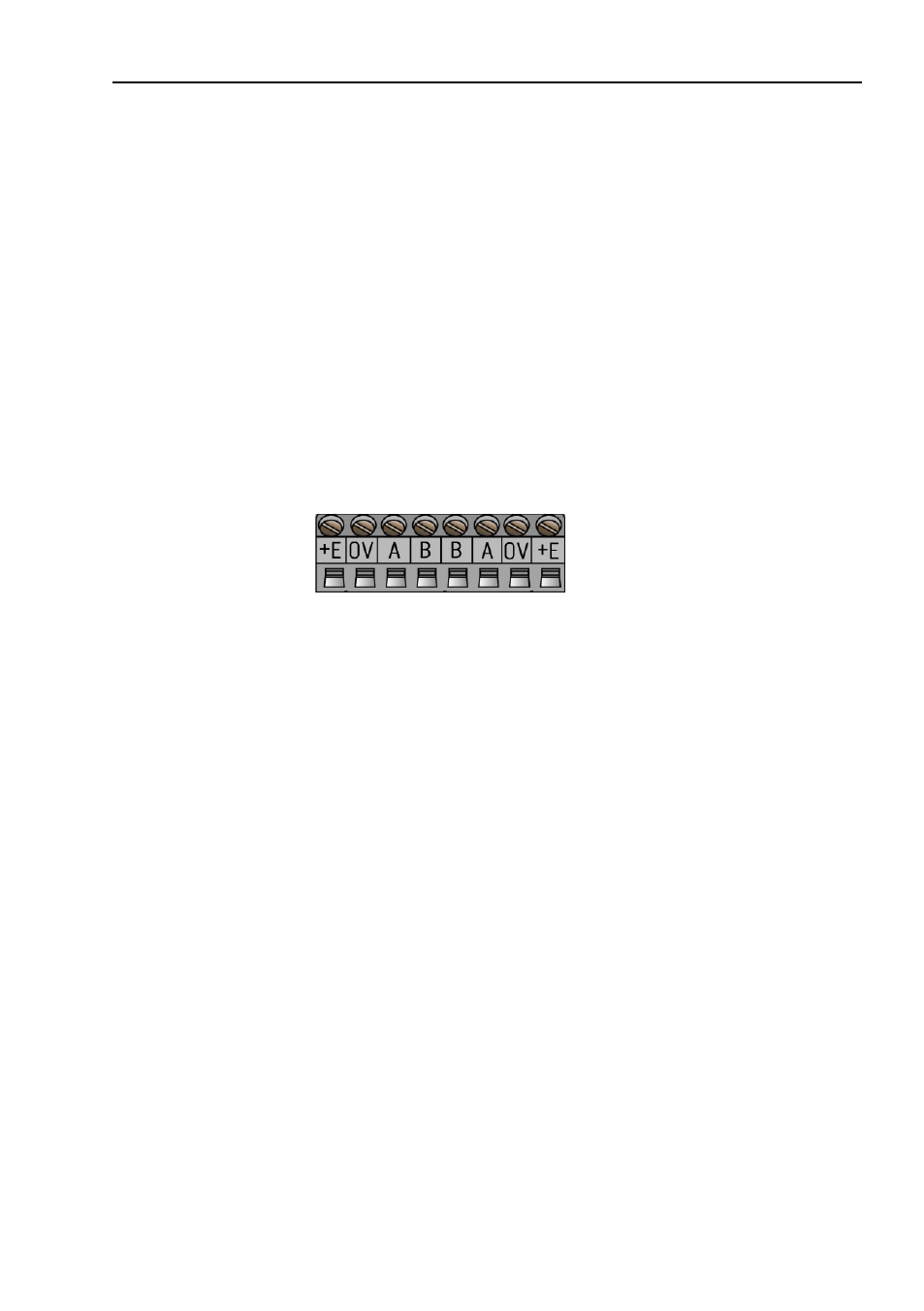
The +E terminal shall be used to connect +E Volt (9-36Vdc).
The 0V terminal shall be used to connect 0 Volt.
Figure 4
Terminal connections of power supply cables
Note: Tighten all screws in the terminal, even if no cable has
been attached.
Note: The two +E terminals are connected to each other and
the two 0V terminals are also connected to each other,
i.e it does not matter to which pair the +E Volt and
0Volt are connected to.