Introduction, Measuring the basic rotation – HEIDENHAIN iTNC 530 (340 49x-05) User Manual
Page 525
HEIDENHAIN iTNC 530
525
14.7 Compensating W
o
rk
piece Misalignment with a 3-D T
o
uc
h Pr
obe
14.7 Compensating Workpiece
Misalignment with a 3-D Touch
Probe
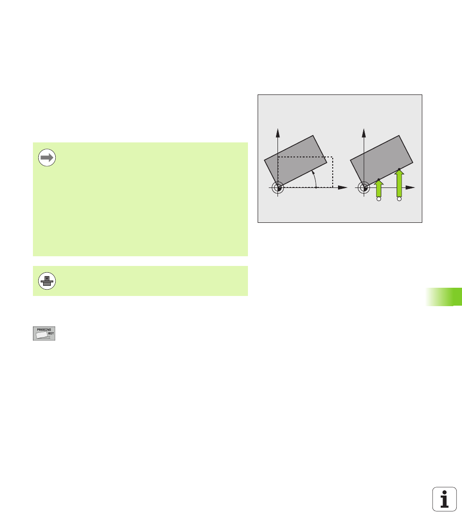
Introduction
The TNC electronically compensates workpiece misalignment by
computing a “basic rotation.”
For this purpose, the TNC sets the rotation angle to the desired angle
with respect to the reference axis in the working plane. See figure at
right.
Measuring the basic rotation
U
Select the probe function by pressing the PROBING
ROT soft key
U
Position the touch probe at a position near the first
touch point
U
Select the probe direction perpendicular to the angle
reference axis: Select the axis by soft key
U
To probe the workpiece, press the machine START
button
U
Position the touch probe at a position near the second
touch point
U
To probe the workpiece, press the machine START
button. The TNC determines the basic rotation and
displays the angle after the dialog Rotation angle =
X
Y
PA
X
Y
A
B
Select the probe direction perpendicular to the angle
reference axis when measuring workpiece misalignment.
To ensure that the basic rotation is calculated correctly
during program run, program both coordinates of the
working plane in the first positioning block.
You can also use a basic rotation in conjunction with the
PLANE function. In this case, first activate the basic
rotation and then the PLANE function.
If you change the basic rotation, the TNC asks you if you
also want to save the changed basic rotation in the active
line of the Preset table when you exit the menu. In this
case, confirm with the ENT key.
If your machine has been prepared for it, the TNC can also
conduct a real, three-dimensional set-up compensation. If
necessary, contact your machine tool builder.