3 tool compensation, Introduction, Tool length compensation – HEIDENHAIN iTNC 530 (340 49x-05) User Manual
Page 182: 3 t ool compensation 5.3 tool compensation
182
Programming: Tools
5.3 T
ool Compensation
5.3 Tool Compensation
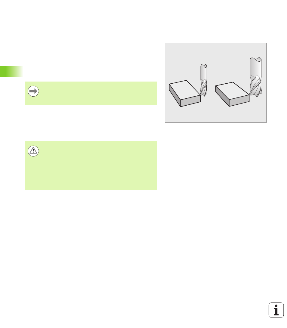
Introduction
The TNC adjusts the spindle path in the spindle axis by the
compensation value for the tool length. In the working plane, it
compensates the tool radius.
If you are writing the part program directly on the TNC, the tool radius
compensation is effective only in the working plane. The TNC
accounts for the compensation value in up to five axes including the
rotary axes.
Tool length compensation
Length compensation becomes effective automatically as soon as a
tool is called and the spindle axis moves. To cancel length
compensation, call a tool with the length L=0.
For tool length compensation, the control takes the delta values from
both the TOOL CALL block and the tool table into account:
Compensation value = L + DL
TOOL CALL
+ DL
TAB
where
If a part program generated by a CAM system contains
surface-normal vectors, the TNC can perform three-
dimensional tool compensation (see “Three-Dimensional
Tool Compensation (Software Option 2),” page 464).
Danger of collision!
If you cancel a positive length compensation with TOOL
CALL 0
the distance between tool and workpiece will be
reduced.
After TOOL CALL the path of the tool in the spindle axis, as
entered in the part program, is adjusted by the difference
between the length of the previous tool and that of the
new one.
L:
is the tool length L from the TOOL DEF block or tool
table
DL
TOOL CALL
is the oversize for length DL in the TOOL CALL 0
block (not taken into account by the position
display).
DL
TAB
is the oversize for length DL in the tool table.