HEIDENHAIN CNC Pilot 4290 User Manual
Page 319
HEIDENHAIN CNC PILOT 4290
307
6.12.9 Milling
Overview of milling operations
■
Contour milling – roughing, finishing (G840)
■
Area milling – roughing (G845), finishing (G846)
■
Deburring (G840)
■
Engraving (G840)
■
Automatic milling – roughing, finishing
Continued
6.12 Int
er
activ
e
W
o
rking Plan Gener
ation (IWG)
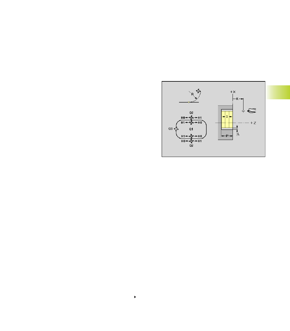
Contour milling – roughing/finishing, deburring
(G840)
Contour milling and deburring are for figure or ”free contours” (open or
closed) of the reference planes:
■
FRONT
■
REAR SIDE
■
SURFACE
The oversize L ”shifts” the milling contour in the direction defined
under ”milling location Q”:
■
Q=0: Oversize is ignored
■
Q=1 (closed contour): Reduces the size of the contour
■
Q=2 (closed contour): Enlarges the contour
■
Q=3 (open contour): Shift left/right – depending on the machining
direction
Parameters
K:
Retraction plane – default: return to starting position
■
Front/rear face: Retraction position in Z direction
■
Lateral surface: Retraction position in X direction (diameter)
Q:
Milling location
■
Q=0 Contour: Cutter center on the contour
■
Q=1 inside (milling) – closed contour
■
Q=2 Outside (milling) – closed contour
■
Q=3 left/right of the contour (reference: machining
direction) – open contour
H:
Cutting direction
■
H=0: Up-cut milling
■
H=1: Climb milling
R:
Approach radius
■
R=0: Directly approach contour element
■
R>0: Approaching/departing radius connecting tangentially
with the contour element
■
R<0 with inside corners: Approach/departure radius
connecting tangentially with the contour element
■
R<0 with outside contours: Contour element is
approached/departed tangentially on a line