7 t u rning cy cles – HEIDENHAIN CNC Pilot 4290 User Manual
Page 138
4 DIN PLUS
126
4.7 T
u
rning Cy
cles
D
G22
G23
G23
G25
G25
G25
=
H0
H1
H4
H5/6
H7..9
0
•
•
•
•
•
•
1
•
•
•
–
–
–
2
•
•
–
•
•
•
3
•
•
–
–
–
–
4
•
•
–
•
•
–
”•”: Skip elements
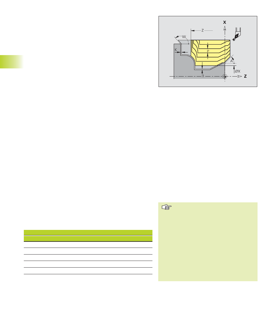
Contour parallel roughing G830
G830 machines the contour area defined by ”NS, NE” parallel to
the contour. The CNC PILOT uses the tool definition to distinguish
between external and internal machining. With ”NS – NE” you
specify the machining direction.
If the contour to be machined consists of one element, then:
■
If you program only NS, machining is in contour def. direction
■
If you program NS and NE, machining is against the contour
definition direction
If required, the area to be machined is divided into several sections,
for example, for machining contour valleys.
The simplest way of programming is specifying NS, NE and P.
Parameters
NS:
Starting block number (beginning of contour section)
NE:
End block number (end of contour section)
P:
Maximum infeed
I:
Oversize in X direction (diameter value)—default: 0
K:
Oversize in Z direction—default: 0
X:
Cutting limit in X direction (diameter value)—default: none
Z:
Cutting limit in Z direction—default: no cutting limit
A:
Approach angle (reference: Z axis)—default: 0°/180° (parallel
to Z-axis)
W:
Departing angle (reference: Z axis)—default: 90°/270°
(perpendicular to Z-axis)
Q:
Type of retraction after machining—default: 0
■
Q=0: Return to starting point (first in X direction, then in Z)
■
Q=1: Position in front of finished contour
■
Q=2: Move to clearance height and stop
V:
Identifier beginning/end—default: 0
A chamfer/rounding arc is being machined:
■
V=0: At beginning and end
■
V=1: At beginning
■
V=2: At end
■
V=3: No machining
■
V=4: Chamfer/rounding is being machined—not the basic
element (prerequisite: Contour section with an element)
D:
Omit element (influences the machining of undercuts, relief
turns: see table)—default: 0
Cycle run
1 Calculate the areas to be machined and the
cutting segmentation (infeeds).
2 Approach workpiece for first pass from starting
point, taking the safety clearance into account.
3 Execute the first cut (roughing).
4 Return at rapid traverse and approach for next
pass.
5 Repeat 3 to 4 until the complete area has been
machined.
6 If required, repeat 2 to 5 until all areas have been
machined.
7 Retract as programmed in ”Q.”
Cutting limitation: The tool position
before the cycle call determines the
effect of a cutting limit. The CNC PILOT
machines the area to the right or to the
left of the cutting limit, depending on
which side the tool has been positioned
before the cycle is called.
Cutter radius compensation: Active
G57 oversize: “Enlarges” the contour
(also inside contours)
G58 oversize:
■
>0: ”enlarges” the contour
■
<0: is not considered
G57/G58 oversizes are deleted after
cycle end