Grass Valley XtenDD DD User Manual
Page 64
5. Connection and Statup
5 - 2
Planning and Installation - Rev. 3 / 04.2005
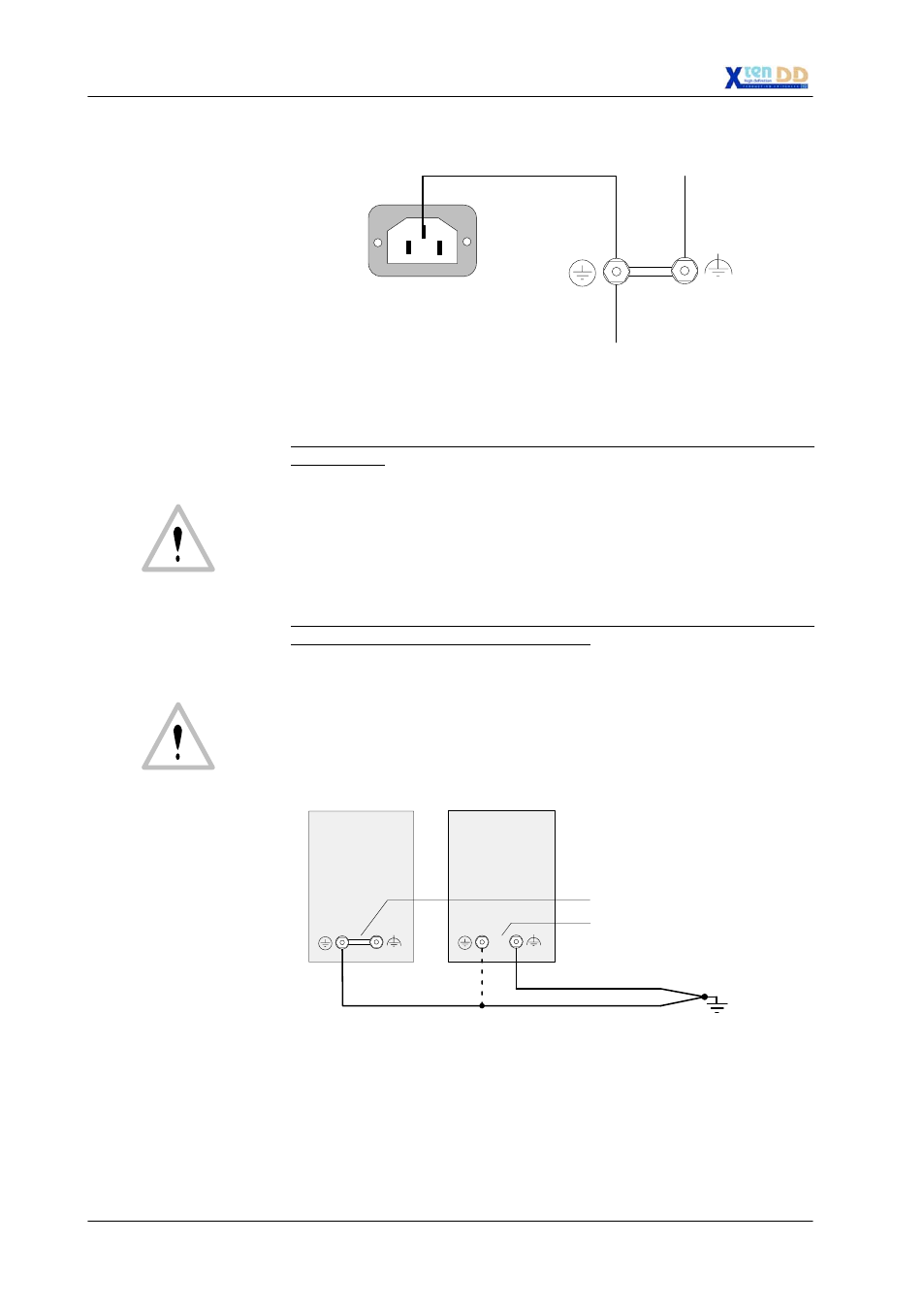
AC IN
Internal protective earth
Video earth
Case
(insulated mounting)
PE
TE
Internal wiring
For additional grounding of the devices, the following methods are possible:
1. As a potential compensation or as an additional earth conductor with large
cross section:
The jumper between the PE and TE terminal screws must be in place. The cen-
tral protective conductors of the studio have to be screwed to the PE terminal
screw. The protective conductor should have a cross section greater than that
of the neutral conductor N of the mains cable, however, 2.5 mm
2
at least (with
protected installation) (4mm
2
with unprotected installation). Fusing up to 25A.
Standards: VDE 0800, part 2, table 1/ VDE 0100 T.540 / IEC 364-5-54, 543.1.
Color code of the insulation: green/yellow.
2. Additional noiseless functional protective earth FPE (functional earth with pro-
tective qualities) low on extraneous voltage:
If required, e.g. in studios with separate protective and technical earth systems,
the jumper between the PE and TE terminals can be broken. In this case, the
central functional earth has to be additionally connected to the TE terminal
screw.
The cross section has to be dimensioned as described above. A low-imped-
ance interconnection of both earth conductors must be provided at the central
studio grounding point or at the earth bus.
Protective earth
Video earth
Central
earthing point
Device
Example 1
Device
Example 2
Jumper not broken!!
Jumper broken!!
TN-C power systems
In case of TN-C power systems (combination of neutral conductor and protective
conductor), it is necessary to observe the regulations in conformity with IEC
364-5-54 (VDE 0100 T-540) and IEC 364-4-41, IEC 364-4-47 (VDE 0100 T.410)
or the applicable national regulations.