Grass Valley XtenDD DD User Manual
Page 136
7. Initial Installation
7 - 6
Planning and Installation - Rev. 3 / 04.2005
7.2.1
POWER SUPPLY
The switchers are not provided with a central power switch. Switching on
and off is made via the central mains distribution of the studio or the equip-
ment cabinet!
For service works plug out the power cables of the mainframe and the control
panel.
After having switched on the line voltage, a self-test is carried out in the mainframe
controller and panel controller.
The correct functioning of controller RY 3156 is indicated by a running light in the
two LED rows.
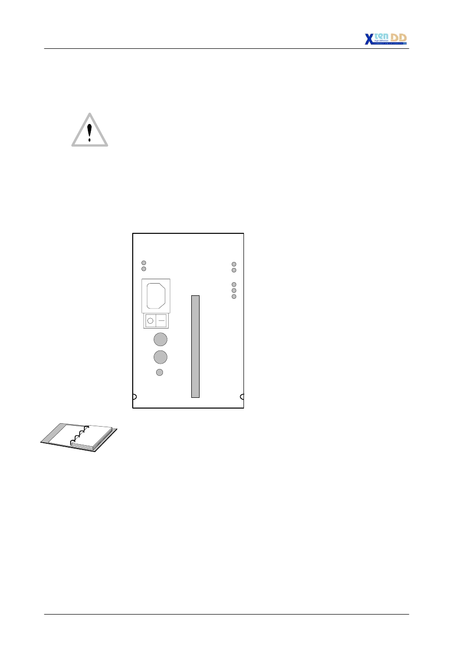
Functioning of the power supply is indicated by the ”green” LEDs. For each main
line of the voltage distribution in the support frame, a separate LED is available.
POWER
AC-OK
5V
V out-OK
Fans-OK
3.3V-1
3.3V-2
12V
AC IN
250V
T10A
250V
Front
End
POWER SUPPLY
RC 3009
T10A
Front panel LEDs:
AC OK
green
mains fuse in order
off
fuse defective or no line voltage
Vout OK green
all output voltage in order
off
one or more output missing
Fans OK green
internal fan in PS module in order
off
internal fan defective
Frontend off
module in order
red
module overloaded
PS1(red) PS1 PS2(red) PS2
3.3V-1
+3.3VD2 +3.3VD2 +3.3VD4 +3.3VD4
3.3V-2
+3.3VD1 +3.3VD1 +3.3VD3 +3.3VD3
5V
+5VD1 +5VD1 +5VD2 +5VD2
THOMSON
If the LED rows of the controller indicate a defined error code, please refer to the
section ”Diagnosis” in the service manual.
In the control panel, all button lamps are lit temporarily. Subsequently, the control
panel returns to the operational state achieved before switching off.
If the LED ”No Reference” on the plug-in card RY 3030 is lit red, make sure that the
switcher receives an external reference signal and press the RESET key.
The status LEDs are switched off when switching on or performing a RESET. After
run of a diagnosis, the LEDs are lit to indicate correctly operating p.c. boards.
Note
Switching on
No Reference