Grass Valley XtenDD DD User Manual
Page 60
4. Installing Control Panels
4 - 22
Planning and Installation - Rev. 3 / 04.2005
D
Put in the extended main panel in the cutout. For fastening, bores are provided
in the frame. The frame can be fastened with countersunk wood screws with
a diameter of 4 mm. The length of the screw depends on the plate thickness
of the desk. A set with mounting parts is included in the delivery of the switcher.
D
Note for mounting the display side panel:
Connect the three cables first on the rear panel of the display side panel before
put in the display mounting frame in the the “All-in-one” mounting frame!
D
Put in the mounting frame of the side panels. For fastening , bores are provided
in the frame of each mounting frame. The respective frame can be fastened
with countersunk screws with a diameter of 4 mm. A set with mounting parts
is included in the delivery of the switcher.
D
Connect the flat cables into the corresponding plugs of the modules.
D
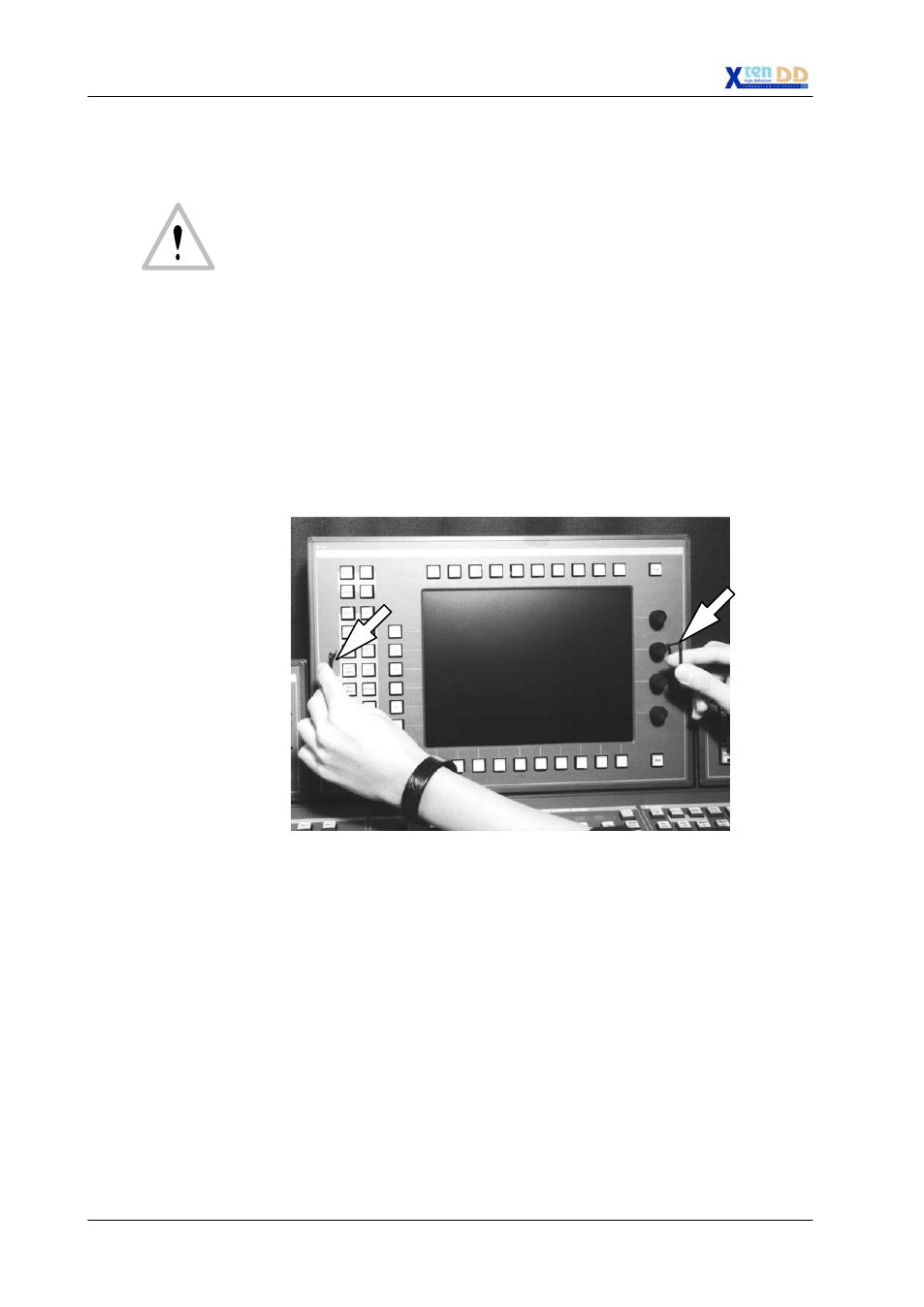
Put in the side panel modules in in the mounting frames. By pressing, the mod-
ules engages independently. The locking mechanism can be removed by the
two release tools (in panel accessory pack). Therefore the module can be re-
moved very simply from the mounting frame. After mounting the panels please
close all locking holes witch the plastic caps delivered in the accessory pack.
release
tools
D
Depending upon cable routing and clearances, you may want to attach control
panel cabling before you lower the panel into the cutout.