Grass Valley XtenDD DD User Manual
Page 176
8. Installation External Devices
8 - 2
Planning and Installation - Rev. 3 / 04.2005
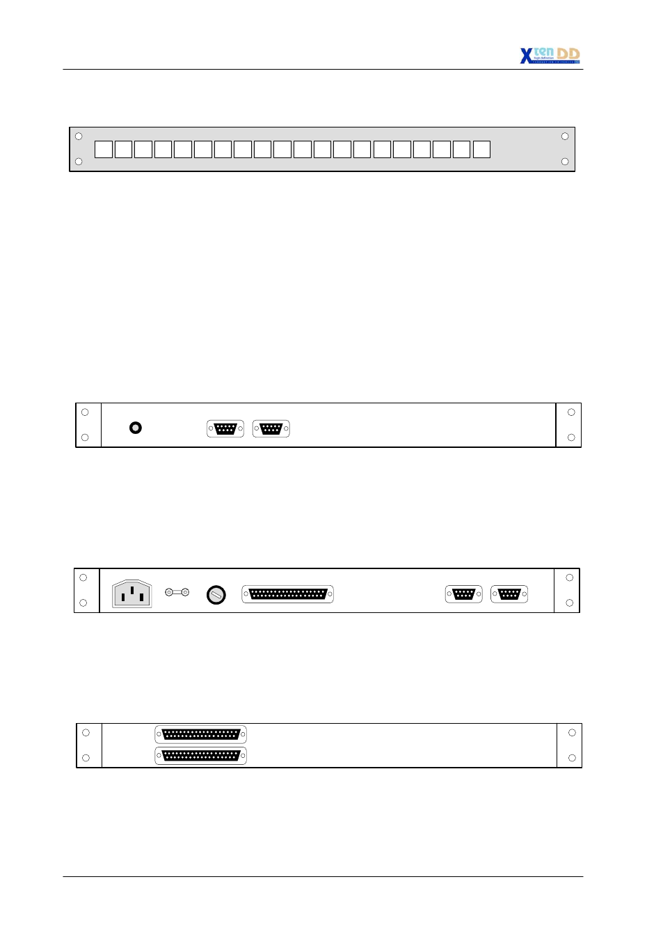
20 source selection buttons for CP-3020 extension (19”, 1HE, large buttons)
THOMSON
CP-3021 Control Panel
CP-300 and CP-330 were already used by all DD production switchers families.
All Aux control panels are “MPK Bus” devices. The panels sit on our message-per-
keystroke “MPK Bus” for control panel communication. This serial data bus can
support up to sixteen 300-series panels daisy-chained on a single serial port of the
switcher mainframe or control panel. Looping connectors are provided to simplify
daisy chaining connections.
The rear panels of each CP-300 and CP-330 control panels are identical. Each one
has a power receptacle on the left side for input from the +5V DC supply. Two MPK
bus connectors are adjacent for looping the common control panel cable from unit
to unit and to the switcher mainframe or main panel.
DC 5V 600mA
Rear View CP-300, CP-330
MPK
The rear panel of the CP-3020 control panel has a power receptacle on the left side
for input from the AC power supply. Two MPK bus connectors DATA A are adjacent
for looping the common control panel cable from unit to unit and to the switcher
mainframe or main panel. The remote connector is used for connecting the
CP-3021 expansion module.
POWER IN
Rear View CP-3020
FUSE
REMOTE
TE / PE
DATA A
The CP-3021 expansion panels are connected directly to the CP-3020 main control
panel module on a proprietary parallel bus. Two connectors are provided to easily
daisy-chain multiple expansion modules (max. 4) to the main panel. The CP-3021
expansion panels need no separate power supply.
Rear View CP-3021
OUTPUT
INPUT
CP-3021
Panel
Communications
Panel
Connectors