1ru control panels, Introduction – Grass Valley CR Series v.3.2 User Manual
Page 52
40
Introduction
Features
•
A control panel mounts easily and quickly on a router (or remote panel module) enclosure
with two knurled screws and an electrical connector. Connectors for the 1RU panels have 40
pins; connectors for the 2RU panels have 60 pins.
It is not possible to connect a 1RU panel to a 2RU router or remote panel module, or vice
versa.
1RU Control Panels
The CP1616 control panel can connect to, and control, any of the 16×16 routers. It can also
connect to an RP16 remote panel module and control a network of mixed compact routers.
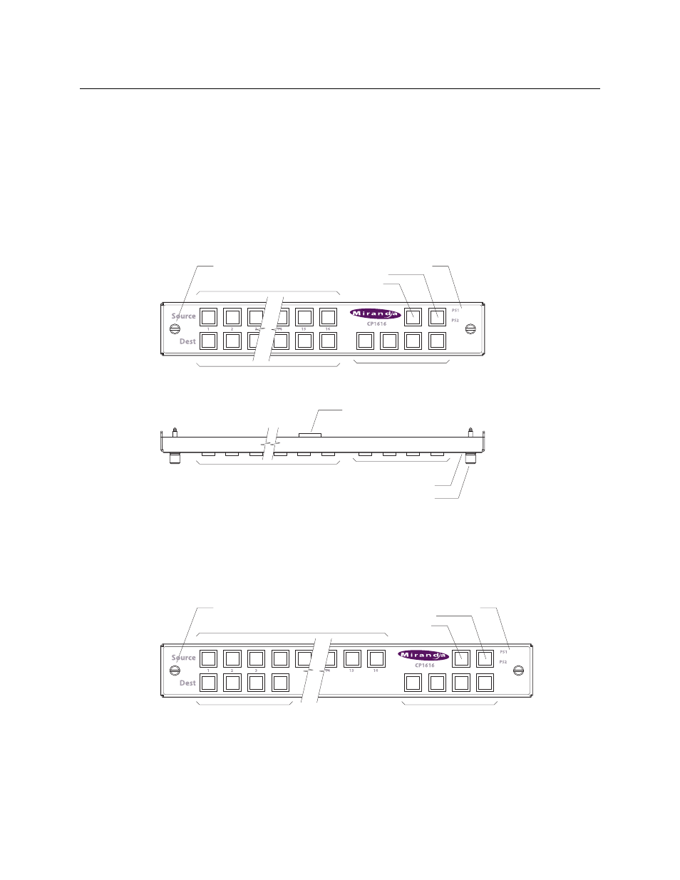
Figures 2-63 and 2-64 show the 16×16 control panel features as used in a stand-alone system:
Fig. 2-63: Front View, CP1616
Fig. 2-64: Top View, CP1616
In CRSC systems, the buttons are all configurable except the lock buttons. In NV9000 systems, all
the buttons are configurable.
The CP1604 or the CP1602 control panel can connect to, and control, a 1RU router and can also
connect to an RP16 remote panel module and control a network of mixed compact routers.
Figures 2-65 and 2-66 show the 16×4 and 16×2 control panel features:
Fig. 2-65: Front View, CP1604
16 Source Buttons
16 Destination Buttons
Knurled Screws (2)
Power Supply LEDs
Panel Lock
Dest. Lock
Levels 14, from left to right
Power Supply LEDs (2)
Knurled Screws (2)
Source and Destination Buttons
Function buttons
Connector to Router
16 Source Buttons
4 Destination Buttons
Knurled Screws (2)
Power Supply LEDs
Panel Lock
Dest. Lock
Levels 14, from left to right