Analog video routers – Grass Valley CR Series v.3.2 User Manual
Page 29
17
CR Series
User’s Guide
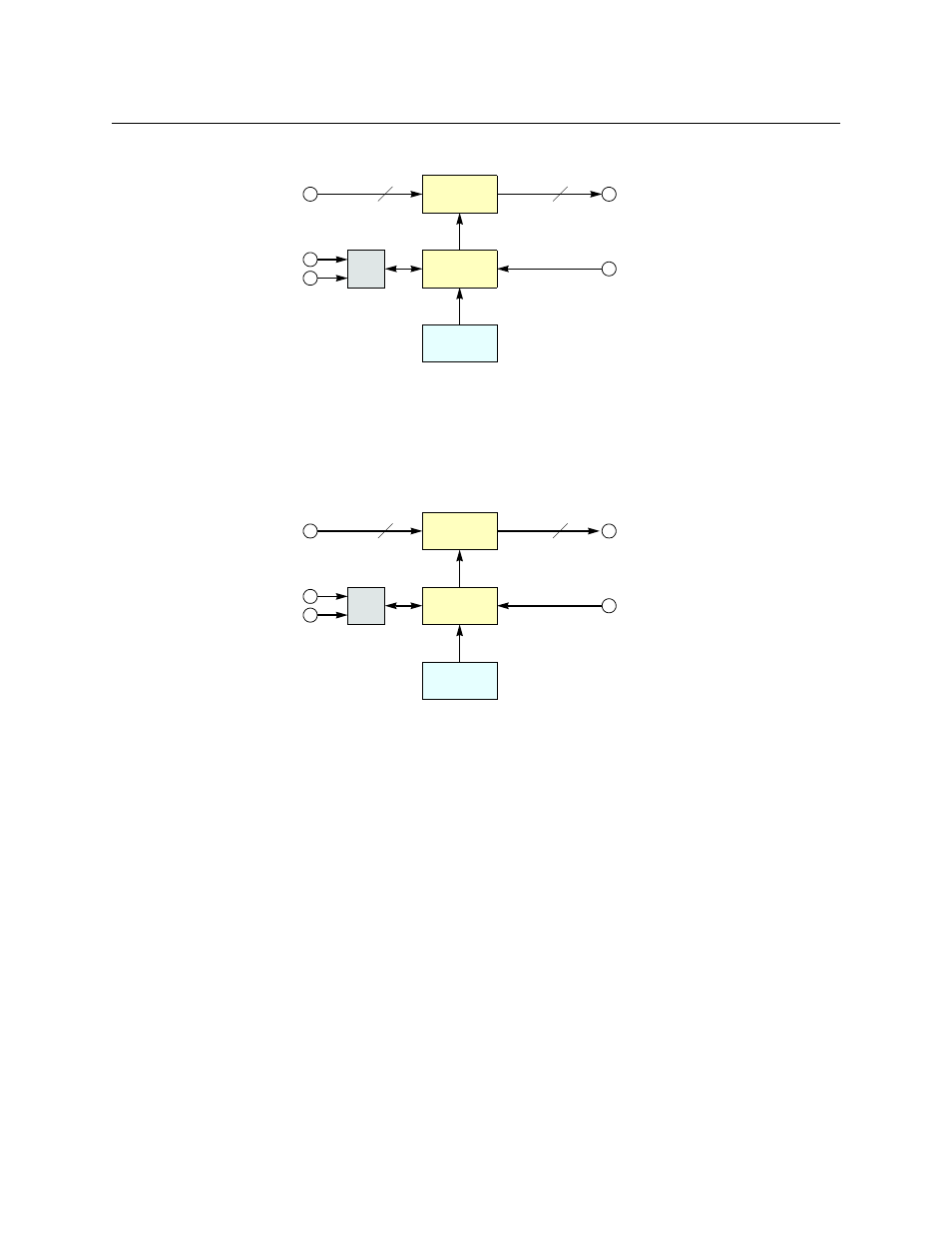
Figure 2-18 shows a simplified block diagram of a CR Series router:
Fig. 2-21: Block Diagram of the CR Series
Analog Video Routers
The 1RU analog video routers have 16×16, 16×4, or 8×8 crosspoints. The 2RU analog video
routers have either 32×32 or 32×4 crosspoints.
Figure 2-22 shows a simplified view of an analog video router:
Fig. 2-22: Block Diagram of the Analog Video Router
The analog video routers switch NTSC (525i) or PAL (625i) video signals. The router outputs are
switched in sync with an external video reference if it is present.
64
64
μP
Logic
Inputs
(Equalized)
Outputs
(Reclocked)
Crosspoint
Switch
Control
Panel
Video
Reference
Serial
Ethernet
(optional)
M
N
μP
Logic
Inputs
Outputs
Crosspoint
Switch
Control
Panel
Video Refer-
ence
Serial
Ethernet
(optional)
M = 8, 16 or 32
N = 4, 8, 16, or 32