2ru routers – Grass Valley CR Series v.3.2 User Manual
Page 43
31
CR Series
User’s Guide
There are 16 normal inputs, 2 emergency bypass inputs, 2 CQX outputs, and 6 aux outputs. The
bypass inputs are switched to the CQX output in the event of a power loss. (The bypass relays
switch when power is removed.)
The GPIO connector supports 16 TTL-level inputs and 4 high-power outputs. All are optically
isolated. See
GPIO Connections for CQX Digital Video Routers
2RU Routers
CR6400 Routers
The CR6400 routers (the CR6464-3Gig and the CR6464-AES) are of modular construction. They
have removable control cards, crosspoint cards, and fan modules. They have 4 I/O card slots into
which I/O cards can be inserted. Presently there are two card types: 3Gig and AES. If a router is
populated with one or more AES card, it is considered a CR6464-AES; if it is populated with one
or more 3Gig (video) cards, it is considered a CR6464-3Gig.
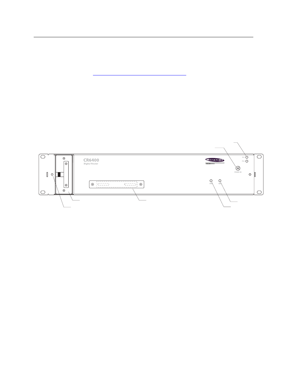
Figures 2-50 and 2-51 show the CR6400 router features.
Fig. 2-50: Front View, CR6400 Router
Visible at the rear of the CR6400 routers are the (removable) crosspoint card, control card, and 4
removable I/O cards. The control card provides an RJ45 Ethernet connector, an RS-485 serial
connector, and loop-through video reference connectors.
Each I/O card has 32 DIN 1.0/2.3 (“coax”) connectors. The 16 at the left are inputs; the 16 at the
right are outputs. Thus the router has a total of 64 inputs at the left and 64 outputs at the right.
Two I/O card types exist presently: an AES card and a 3Gig card. I/O cards must not be mixed in a
router frame.
Screw Holes for Control Panel (2)
Cover Plate over Control Panel
Connectors
16-Pos. Rotary Switch
Power LEDs (2)
Fan Module (Removable)
Video Reference LED
Fan Alarm LED