Inputs, Outputs, Inputs outputs – Grass Valley CR Series v.3.2 User Manual
Page 142: Technical details

130
Technical Details
Connectors
Inputs
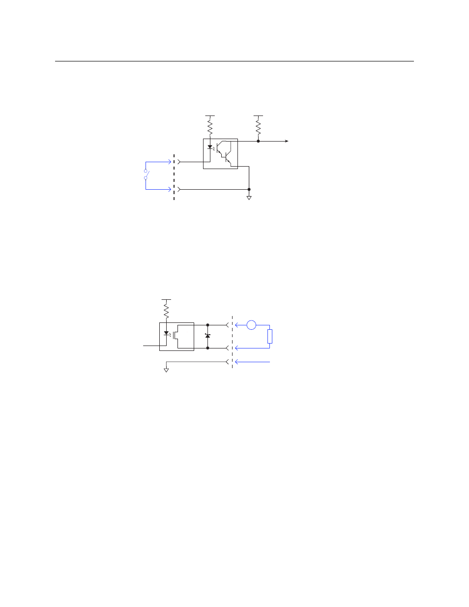
Each input circuit has an individual signal connection, but all the inputs share a single ground
connection:
The input turns on (a positive-going pulse) when the signal is connected to ground (on the
connector). The positive-going pulse on input N switches video input N to CQ output 1, where
1
< N < 16.
The router firmware debounces the inputs and requires about 100 ms between the positive
edges of pulses.
Outputs
The output circuit requires an external voltage source:
The Schottky diode across the output limits applications to less than 30 VDC.
The outputs represent alarm states.
•
Output 1 (power supply).
If you have connected two power supplies and one malfunctions or is disconnected, output
1 signals an alarm.
•
Output 2 (video reference).
If the router has no video reference or the video reference is disconnected, output 2 signals
an alarm.
•
Output 3 (fans).
If any of the fans stop turning, output 3 signals an alarm.
•
Output 4 (bypass).
If the router has no power at all, output 4 signals an alarm. (This condition can occur if both
power supplies fail or are disconnected or if main power fails.)
A GP output turns off to signal an alarm condition. When the CQX router is running properly, all 4
GP outputs are on.
+3.3V
Optical
Isolation
C
E
+3.3V
Input n
to internal bus
10K
Customers
Switch (or
Equivalent
Logic)
MOCD223-M
3.24K
Optical
Isolation
Customers Load
+2.5V
121
+
from
internal bus
Output n
V
Optional Grounding
PS7221A-2A
30V
