Destination lock, Operating a stand-alone router, Operation – Grass Valley CR Series v.3.2 User Manual
Page 100: Locked destination

88
Operating a Stand-Alone Router
Operation
When the control panel is locked, the lock button is bright red and the state of the entire control
panel is protected. Changes from the control panel are disabled. The panel lock button is low
tally green when the control panel is not locked.
Destination Lock
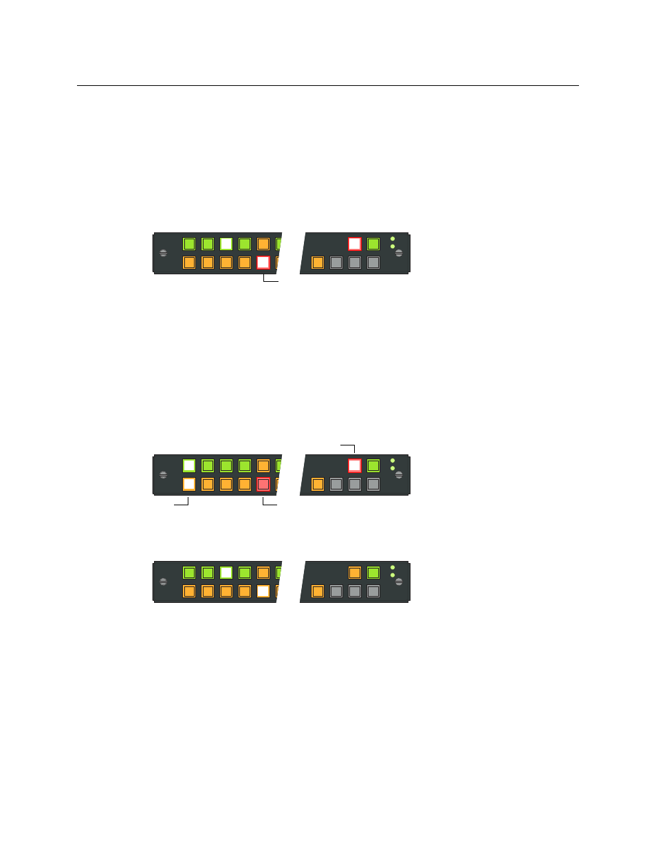
Destination lock prevents selecting another source for the currently selected destination. To
lock a destination, press the destination button, then press Destination Lock. This sample shows
DST 5 locked to SRC 3:
The Destination Lock button immediately goes high tally red and the current source and desti-
nation are high tally, with the destination button red. Changes to that destination are disabled.
If you subsequently press a destination button that is locked, the button goes high tally (red), its
source goes high tally (green) and the Destination Lock button goes high tally, as this sample
shows.
Changes to other destinations are, however, enabled, and specifically, you can route the source
that feeds a locked destination to any number of other destinations.
After you select another (unlocked) destination, the locked destination goes low tally red. This
illustration shows DST 1 selected and DST 5 locked. Because DST 1 is not locked, the Destination
Lock button is low tally amber.
To unlock a destination, press the destination button and then press Destination Lock (again).
The destination button reverts to amber and the Destination Lock button goes low tally. This
illustration shows DST 5 selected and no longer locked:
Source
Dest
1
2
3
4
5
6
MON
VTR
2
VTR
3
VTR
1
PNL
LOCK
DST
LOCK
DST
LOCK
Locked Destination
Source
Dest
1
2
3
4
5
6
MON
VTR
2
VTR
3
VTR
1
PNL
LOCK
DST
LOCK
DST
LOCK
Locked Destination
Destination Lock
Selected Destination
Source
Dest
1
2
3
4
5
6
MON
VTR
2
VTR
3
VTR
1
PNL
LOCK
DST
LOCK
DST
LOCK
