35 cr series, The 32×4 analog audio router has 4 output (pairs), User’s guide – Grass Valley CR Series v.3.2 User Manual
Page 47
35
CR Series
User’s Guide
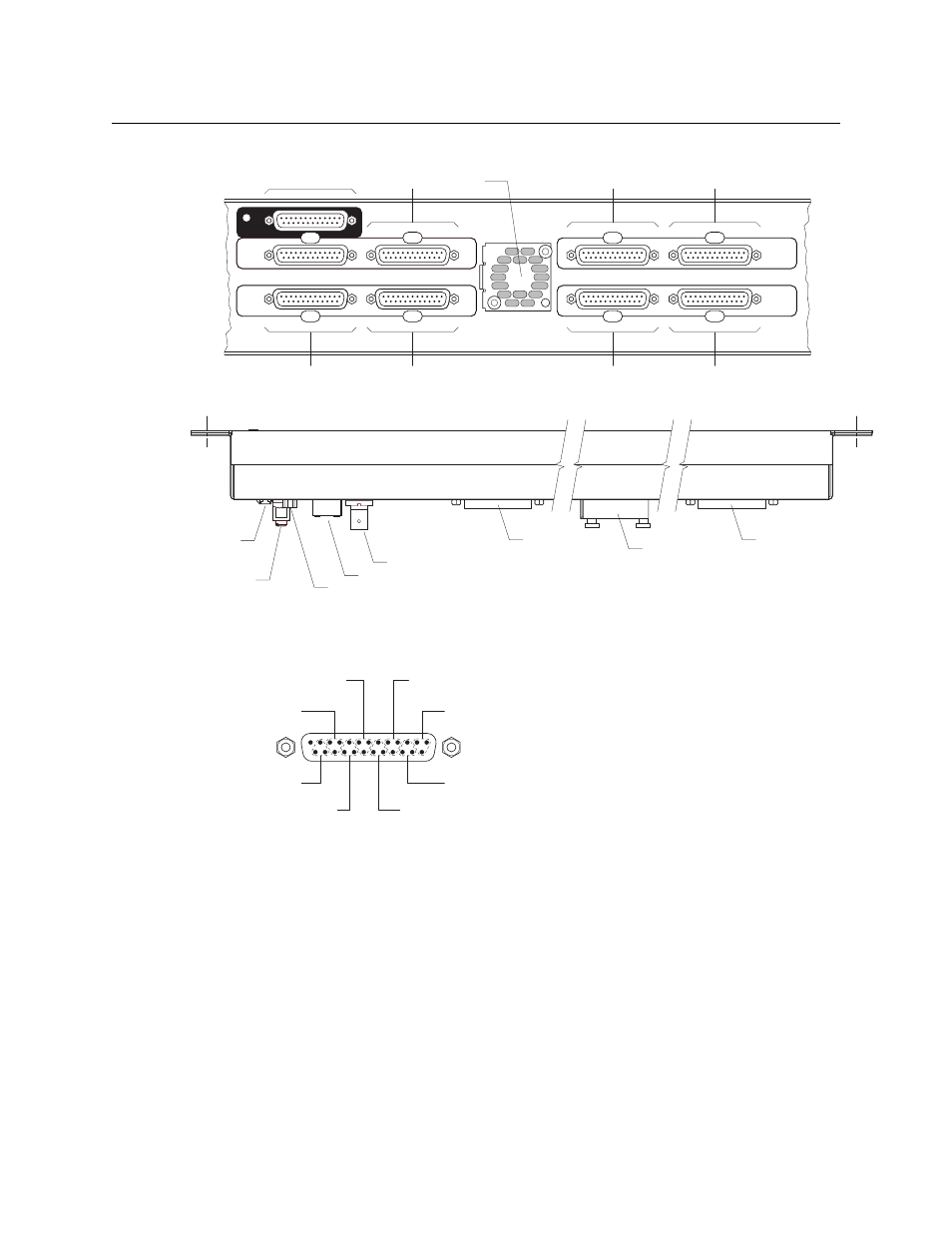
The 32×4 analog audio router has 4 output (pairs):
Fig. 2-59: Rear View, 32×4 Analog Audio Router
Fig. 2-60: Top View, 2RU Analog Audio Router
Analog inputs are in the middle; analog outputs are at the top and bottom (in the dark regions).
Each DB25 connector supports 8 inputs (or outputs):
The 8 input connectors provide inputs 1–8, 9–16, 17–24, 25–32, 33–40, 41–48, 49–56, and 57–64,
respectively, and are labelled that way on the rear of the router. Inputs are treated as 32 stereo
pairs.
The same is true for the outputs.
The 2RU analog audio router also has a small fan.
INPUTS
INPUTS
17-24
25-32
OUTPUTS
1-8
9-16
INPUTS
INPUTS
33-40
41-48
49-56
57-64
Inputs 1724
Inputs 2532
Inputs 916
I/O18
Fan
Inputs 3340
Inputs 4956
Inputs 4148
Inputs 5764
GND
Ethernet
RS-422
Power
connectors
(PS1, PS2)
Video reference
I/O 18,
I/O 1724
Fan
I/O 4148,
I/O 5764
Number
1
2
3
4
5
6
7
8
Stereo Designation
1L
1R
2L
2R
3L
3R
4L
4R
I/O Connections
(n.c.) 13
No. 2
No. 4
No. 8
No. 6
11
23
10
8
20
7
5
17
4
2
14
1
No. 1
No. 3
No. 7
No. 5
25
12
24
22
9
21
19
6
18
16
3
15
1
14
25
GND
+
GND
+
GND
+
GND
+
GND
+
GND
+
GND
+
GND
+