Panel – Grass Valley CR Series v.3.2 User Manual
Page 189
177
CR Series
User’s Guide
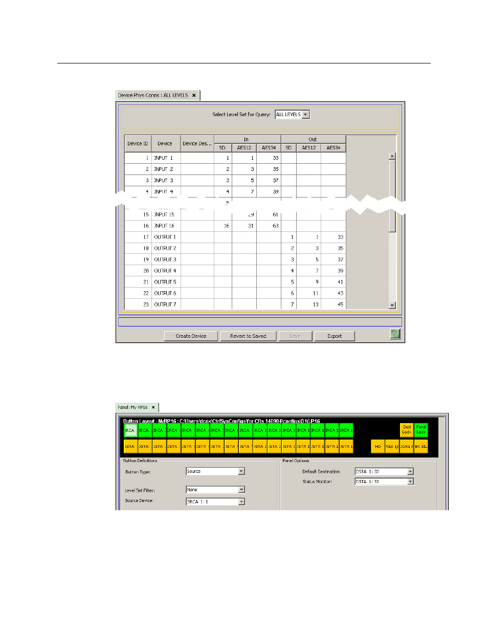
The following table is the result of device entry for this example:
Note that the input and output pairs are represented by the odd-numbered member of the pair.
Panel
This figure shows the panel configuration for the simple example:
The names of your inputs and outputs appear as the button legends here in the configuration
page. The names of your salvos appear here as the button legends. These names do not auto-
matically appear on the actual remote panel. (If the panel is to have button legends, you can
create physical button legend inserts using graphics and text.)
This manual is related to the following products: