Stand-alone cr6400 network, Startup, 109 cr series – Grass Valley CR Series v.3.2 User Manual
Page 121: User’s guide, Locked destination selected destination
109
CR Series
User’s Guide
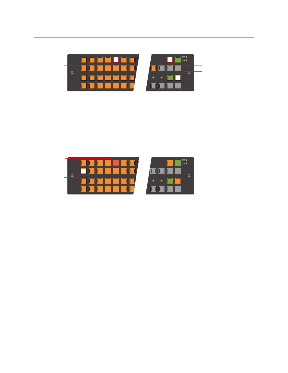
This sample shows destination 5 locked:
(Press ‘Source Mode’ to see the source that feeds the destination. The button for that source is
high-tally.)
If you subsequently press a button for a destination that is locked, the button goes high tally
(red), and the Destination Lock button goes high tally, as this example shows.
Other destinations remain unchanged, whether locked or unlocked, and specifically, you can
route the source that feeds a locked destination to any number of other destinations.
When you select another (unlocked) destination, a locked destination goes low-tally red. This
illustration shows destination 1 selected and destination 5 locked. Because the selected destina-
tion is not locked, the ‘Destination Lock’ button is not red, but low-tally amber.
To unlock a destination, press the selection button for the destination and then press Destina-
tion Lock (again). The selection button for the destination reverts to amber and the ‘Destination
Lock’ button goes low-tally amber.
Stand-Alone CR6400 Network
A stand-alone network includes 1–4 CR Series routers, one CP6464 panel, and an Ethernet
switch.
Startup
To power up a router or a remote panel module, connect the 4-pin connector the power supply
to PS1 or PS2. Then plug the power supply into AC power outlet. If you have chosen to use two
power supplies for redundancy, connect one to PS1 and the other to PS2.
At power-up, a router loads stored program code into its internal FPGA and restores its previous
operational state. (The “state” includes the crosspoint map between inputs and outputs and
which of the outputs are locked.)
At power-up, a router detects the presence or absence of a video reference signal.
At power-up, routers “discover” the presence and state of other routers in the network.
At power-up, a control panel’s ‘Panel Lock’ button is on (red). You must turn ‘Panel Lock’ off
before you can use the panel.
49 50
51 52 53 54 55
33 34 35
36
37
38 39
17 18 19 20 21
22 23
1
2
3
4
5
6
7
MON
1
PNL
LOCK
DST
LOCK
DST
MODE
SRC
MODE
1. Destination Mode
3. Destination Lock
2. Destination
49 50
51 52 53 54 55
33 34 35
36
37
38 39
17 18 19 20 21
22 23
1
2
3
4
5
6
7
PNL
LOCK
DST
LOCK
DST
MODE
SRC
MODE
Locked
Destination
Selected
Destination