Network requirements, Network diagram, Configuration procedure – H3C Technologies H3C S7500E Series Switches User Manual
Page 249

13-8
As you see, port GigabitEthernet 2/0/1 has obtained the dynamic entries generated by DHCP
snooping after it is configured with dynamic IP source guard binding function.
Dynamic IP Source Guard Binding Function Configuration Example 2
Network requirements
z
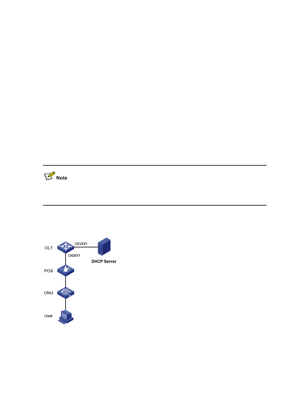
The S7500E switch acting as an OLT device is connected to the DHCP server through
GigabitEthernet 2/0/1 and connected to an ONU through OLT 3/0/1. UNI 1 of the ONU is
connected to a user device.
z
Enable DHCP snooping on the switch.
z
Bind port ONU 3/0/1:1 to the ONU, whose MAC address is 000f-e200-0001.
z
The user device, with the MAC address 00-01-02-03-04-06, obtains an IP address through
the DHCP server. The DHCP snooping entry for the user device is generated on the OLT
device.
z
Enable IP Source Guard on OLT 3/0/1 to protect the server against attacks launched by
clients using fake source IP addresses.
This example shows only
the OLT configurati
on. For DHCP server configuration, see DHCP
Server Configuration in the Layer 3 - IP Services Configuration Guide.
Network diagram
Figure 13-4 Network diagram for configuring dynamic IP source guard binding function II
Configuration procedure
1) Configure the OLT device.
# Enable DHCP snooping.
[Sysname] dhcp-snooping
# Configure GigabitEthernet 2/0/1, which is connected to the DHCP server, as a trust port.
