Vertical and horizontal timing – Ensemble Designs 9430 Flexible Matrix Router for 3G / HD / SD / ASI User Manual
Page 85
www.ensembledesigns.com
Page 85
Avenue 9430 Flexible Matrix Router
Installation, Configuration and Operations Guide
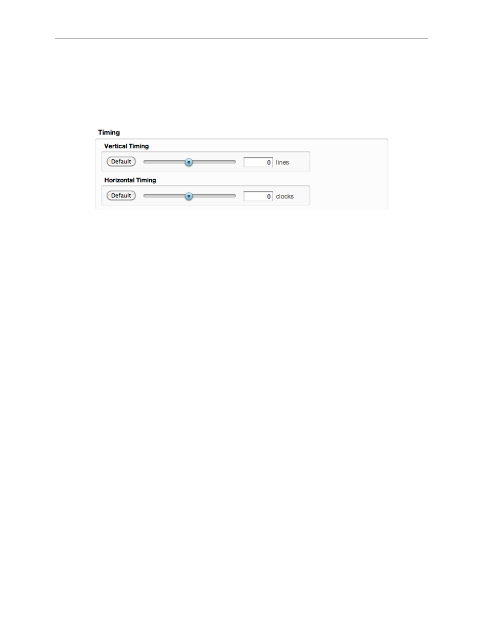
Vertical and Horizontal Timing
This control adjusts the timing of the Clean Switch relative to the genlock reference. Setting the H and
V parameters to 0 will “zero” time the CS, matching it to the reference. Negative values will cause the
CS to be early with respect to the reference; positive values will make the Clean Switch output later in
time.
The best or most appropriate setting for the timing controls will depend upon the way in which the CS
is to be used and the nature of the video inputs.
Note:
A video frame sync imposes delay on a video signal passing through it in order
to align that input to the user adjusted output timing. The amount of delay is a
function of the difference in timing between the incoming video and the output
of the frame sync. The frame sync can only add delay to the video in order to make
up that difference, and the amount will change automatically in accordance with
the timing of the input signal. If the input signal is one line early compared to the
output, the frame sync will add only one line of delay. But if the incoming video is
just one line late, the frame sync will add nearly an entire frame (less one line) to
bring the signal into time. If the input is asynchronous, its timing will be changing
(drifting) continuously. And in that case, the delay imposed by the frame sync will
vary continuously between (near) zero and one frame.
When a Clean Switch is being used as a pre-selector to a production switcher, the CS output timing
must fall within the input auto-time window of the switcher. In general, this will be accomplished by
setting the Clean Switch H and V parameters to zero.
If the Clean Switch is feeding on-set monitors in a live environment from sources also used on
the production switcher, it is generally desirable to minimize the delay on those monitors. This is
accomplished by setting the Vertical timing of the Clean Switch to a small positive value. Setting this
parameter to +4 lines will typically guarantee that the sources (which have near zero timing) will
only experience 2 or 3 lines of delay. Since most production switchers have a forward delay of 1, 2, or
3 lines, a setting of +4 lines on the Clean Switch will also allow the switcher output to be used with
minimum delay.