Working with the clean switch option – Ensemble Designs 9430 Flexible Matrix Router for 3G / HD / SD / ASI User Manual
Page 80
www.ensembledesigns.com
Page 80
Avenue 9430 Flexible Matrix Router
Installation, Configuration and Operations Guide
Working with the Clean Switch Option
Each 9435 Dual Clean Switch Option provides two, independent Frame sync/Clean Switches. These
resources can be deployed within the Router in a variety of ways. The physical location of the
submodule, whether installed on the 9430 core module, or on the 9440 in Expansion 1 position (the
left hand position as viewed from the front of the frame) does not affect where or how each of these
resources are assigned or used.
Note:
Only a 9440 in the Expansion 1 position supports the 9435 Dual Clean Switch.
Although it is mechanically possible to install a 9435 on a 9440 in Expansion 2, that
9435 will not appear as a resource in the configuration menus.
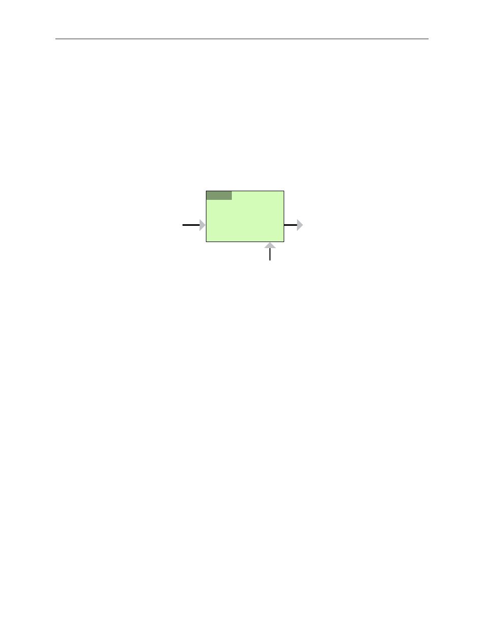
Clean Switch!
/ Framesync
In
Out
Genlock
9435
!
/
1
2
A Clean Switch is a Frame sync whose input and output can be connected to different points within
the Router. The flexibility this provides allows the Clean Switch to be associated with either inputs or
outputs.
The output side of the Clean Switch is genlocked to the reference being used within the Router.
This ensures that the output is stable regardless of the input signal. Not only does this ensure clean
switching between un-timed and even asynchronous sources, it also guarantees a stable, Black output
upon loss of input.
In parallel with the video processing, 16 channels of embedded audio are silently switched as well.
Incoming audio is disembedded, sample rate converted, switched, and then embedded into the
output. The audio processing includes a delay mechanism to compensate for the delay imposed on
the video by the frame sync. This compensation ensures that the time relationship (lip-sync) between
audio and video is maintained.
The configuration of the Clean Switch includes its video format, timing, and embedded audio group
enables.
When a Clean Switch is assigned to an output port, its input is fed from the routing matrix and it drives
the output BNC connector. Any SDI source in the Router switched to this output will be presented
synchronously and timed.