Westermo PMI-110-F2G User Manual
Page 69
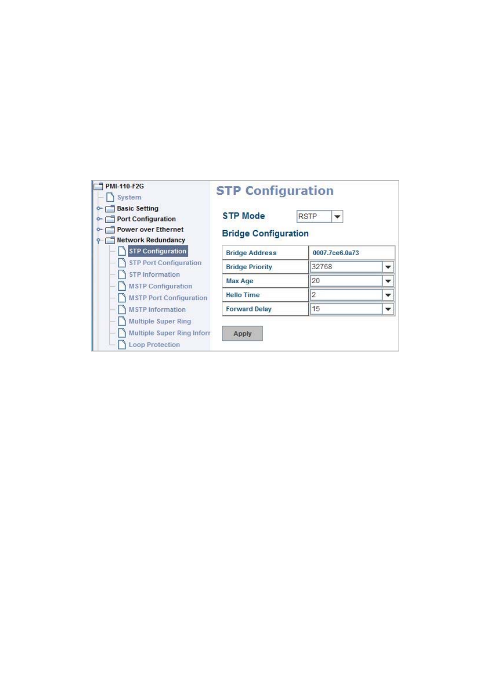
4.5.1 STP Configuration
This page allows select the STP mode and configuring the global STP/RSTP Bridge
Configuraiton.
The STP mode includes the STP, RSTP, MSTP and Disable. Please select the STP
mode for your system first. The default mode is RSTP enabled.
Afte select the STP or RSTP mode; continue to configure the gloable Bridge
parameters for STP and RSTP.
After select the MSTP mode, please go to MSTP Configuration page.
RSTP is the abbreviation of Rapid Spanning Tree Protocol. If a switch has more
than one path to a destination, it will lead to message loops that can generate
broadcast storms and quickly bog down a network. The spanning tree was
created to combat the negative effects of message loops in switched networks. A
spanning tree uses a spanning tree algorithm (STA) to automatically sense
whether a switch has more than one way to communicate with a node. It will
then select the best path (primary), and block the other path(s). It will also keep
track of the blocked path(s) in case the primary path fails. Spanning Tree Protocol
(STP) introduced a standard method to accomplish this. It is specified in IEEE
802.1D‐1998. Later, Rapid Spanning Tree Protocol (RSTP) was adopted and
represents the evolution of STP, providing much faster spanning tree convergence
after a topology change. This is specified in IEEE 802.1w. In 2004, 802.1w is
included into 802.1D‐2004 version. This switch supports both RSTP and STP (all
switches that support RSTP are also backward compatible with switches that
support only STP).
65