3 wiring the relay output (do), Wiring the relay output (do) – Westermo PMI-110-F2G User Manual
Page 17
2.3
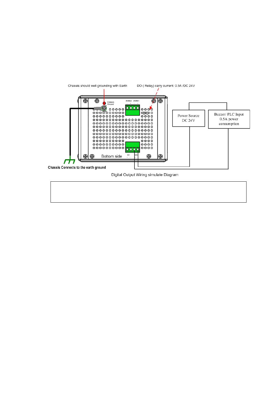
Wiring the Relay Output (DO)
The relay output contacts are in the bottom side as shown on below figure. The relay
output (DO) is controlled by the pre‐defined operating rules. To activate relay output
function, please refer to the CD User’s Manual for more Relay Output management
information.
Note: The relay contact only supports 0.5 A current, DC 24V. It is not recommended to apply
voltage and current higher than the specifications.
13
See also other documents in the category Westermo Equipment:
- TR-36B (88 pages)
- TD-36 (44 pages)
- TR-36 (36 pages)
- TR-36B (20 pages)
- IDW-90 AT (97 pages)
- GD-01 (206 pages)
- GD-01 (20 pages)
- MRI-128-F4G (175 pages)
- MRI-128-F4G (169 pages)
- GDW-11 485 (380 pages)
- GDW-11 (40 pages)
- Lynx Series (28 pages)
- ODW-720-F1 (20 pages)
- ODW-720-F1 (24 pages)
- ODW-720-F2 (36 pages)
- ODW-730-F2 (36 pages)
- ODW-730-F1 (24 pages)
- DDW-120 (24 pages)
- DDW-226-EX (24 pages)
- DDW-226-EX (24 pages)
- DR-270 (28 pages)
- DR Series (460 pages)
- ED-2x0 (20 pages)
- MRD-3x0 (199 pages)
- FD-80 (24 pages)
- FDV-206-1D-1S (24 pages)
- GD-01 US (24 pages)
- LD-01 (8 pages)
- IDW-90 (44 pages)
- Lynx-x10-F2G (16 pages)
- Lynx-x08-F2G-S2 (20 pages)
- MDI-110-F3x (16 pages)
- MR-2x0 (28 pages)
- ODW-642 (28 pages)
- PII PoE Injector (12 pages)
- Viper Series (977 pages)
- SDI-5xx (12 pages)
- RFI-xx (32 pages)
- SDI-8xx (16 pages)
- RFIR-xxx (24 pages)
- TD-29 (16 pages)
- SDW-5xx (24 pages)
- TD-23 (24 pages)
- TD-29P (16 pages)
- Viper 408 (20 pages)