4 wiring the digital input (di), Wiring the digital input (di) – Westermo PMI-110-F2G User Manual
Page 18
2.4
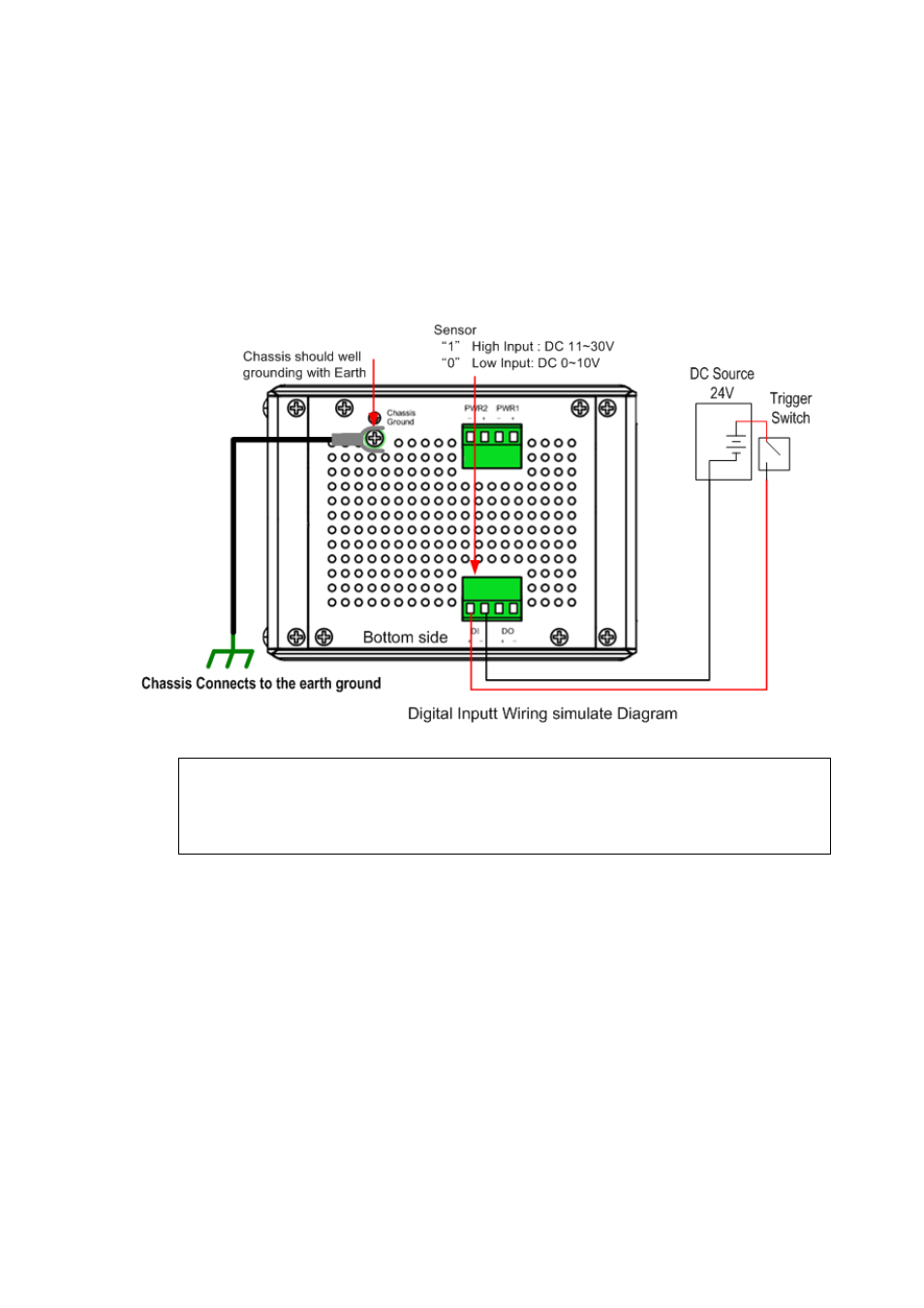
Wiring the Digital Input (DI)
The Digital Input (D.I.) contacts are in the bottom side of the device as shown in
below figure.
It accepts one external DC type signal input and can be configured to send alert
message through Ethernet when the signal is changed. The signal may trigger and
generated by external power switch, like as door open trigger switch for control
cabinet.
Note: the DI accepts DC type signal and supports isolated input circuit with Digital High
Level input DC 11V~30V and Digital Low Level input DC 0V~10V. Do not apply voltage that
higher than the specification; it may cause internal circuit damage or a wrong action of DI.
14
See also other documents in the category Westermo Equipment:
- TR-36B (88 pages)
- TD-36 (44 pages)
- TR-36 (36 pages)
- TR-36B (20 pages)
- IDW-90 AT (97 pages)
- GD-01 (206 pages)
- GD-01 (20 pages)
- MRI-128-F4G (169 pages)
- MRI-128-F4G (175 pages)
- GDW-11 485 (380 pages)
- GDW-11 (40 pages)
- Lynx Series (28 pages)
- ODW-720-F2 (36 pages)
- ODW-720-F1 (20 pages)
- ODW-720-F1 (24 pages)
- ODW-730-F2 (36 pages)
- ODW-730-F1 (24 pages)
- DDW-120 (24 pages)
- DDW-226-EX (24 pages)
- DDW-226-EX (24 pages)
- DR-270 (28 pages)
- DR Series (460 pages)
- ED-2x0 (20 pages)
- MRD-3x0 (199 pages)
- FD-80 (24 pages)
- FDV-206-1D-1S (24 pages)
- GD-01 US (24 pages)
- LD-01 (8 pages)
- IDW-90 (44 pages)
- Lynx-x10-F2G (16 pages)
- Lynx-x08-F2G-S2 (20 pages)
- MDI-110-F3x (16 pages)
- MR-2x0 (28 pages)
- ODW-642 (28 pages)
- PII PoE Injector (12 pages)
- Viper Series (977 pages)
- SDI-5xx (12 pages)
- RFI-xx (32 pages)
- SDI-8xx (16 pages)
- RFIR-xxx (24 pages)
- TD-29 (16 pages)
- SDW-5xx (24 pages)
- TD-23 (24 pages)
- TD-29P (16 pages)
- Viper 408 (20 pages)