Table 3.30, Fms mapping menu options – RLE FMS V.1.13 User Manual
Page 118
118
FMS User Guide
800.518.1519
3
Web Interface Configuration
3
At the very bottom of the Input or Relay Configuration screen you’ll see several mapping
fields. a field labeled Map Coordinate: X, Y and a Graphical Mapping link. Click the
Graphical Mapping link.
Figure 3.59
FMS Mapping Fields
These options have the following functions:
4
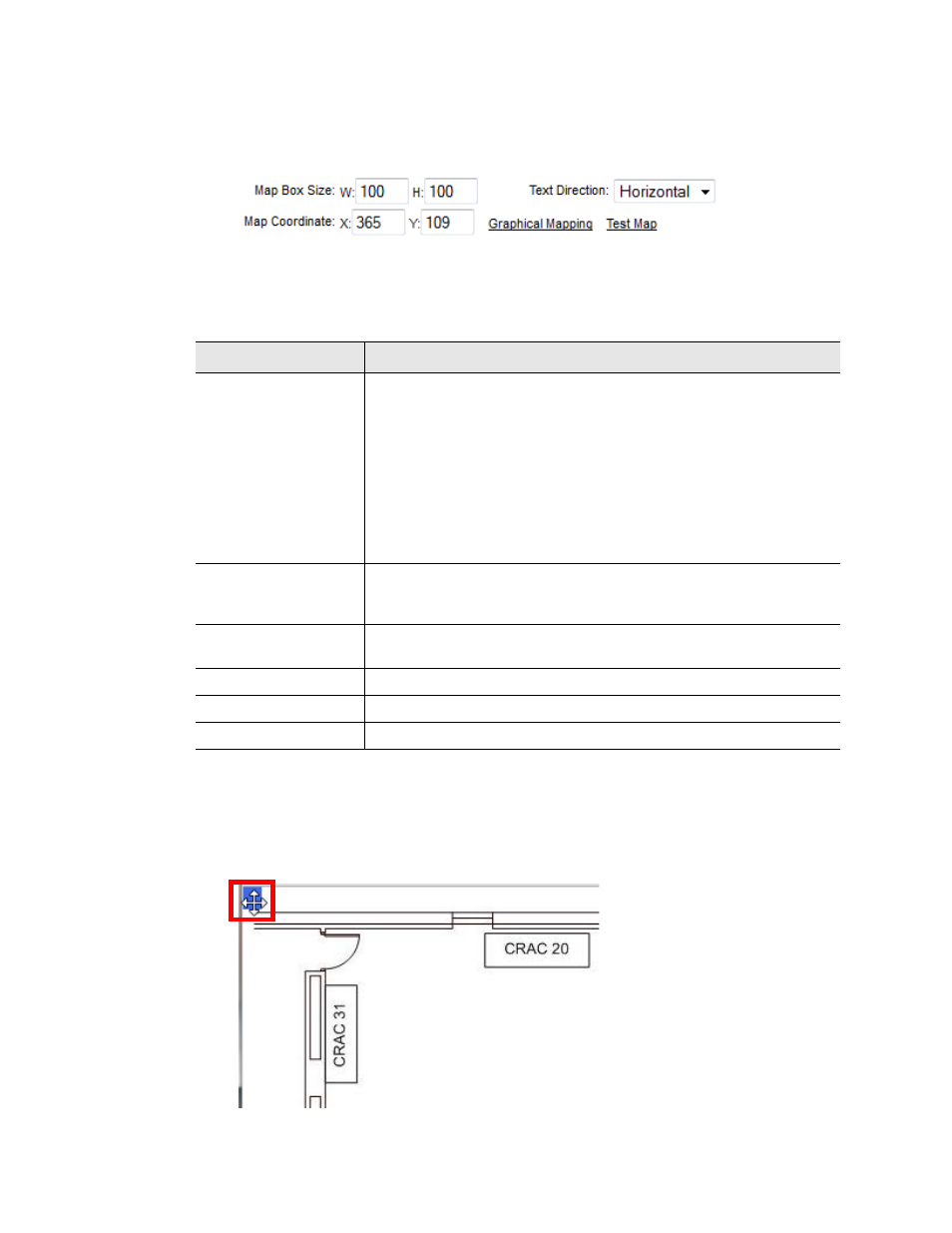
The Graphical Mapping link takes you to a view of your map image. This is where you’ll
designate the physical location of your input or relay. Look at the upper left corner of the
map and locate the blue box. This blue box represents the location of the point you are
mapping, and its blue color indicates you are in mapping configuration mode. Use your
mouse to drag and drop it where you’d like it to appear on your map.
Figure 3.60
FMS Mapping Configuration Mode - Drag and Drop Your Point
Option
Description
Map Box Size
(Inputs Only)
The size of the box that represents the input will default to the size
and shape of the text it contains - usually the value of the input
followed by the unit of measure assigned to it. Sometimes, you may
like to adjust the size of the box to fill an area, rather than just be
the size of the text. This option allows you to do that.
By default, the height of the object, as it appears on the map, is
approximately 20 pixels, and the width automatically adjusts to the
length of the text. If you wish, use this setting to expand the size of
the object to fill a defined area.
Text Direction
(Inputs Only)
Decide if you’d like the text on the map for this object (temperature
reading, humidity reading, sensor value, etc.) to be horizontal or
vertical.
Map Label (Relays
Only)
Designate a map label for the relay.
Map Coordinate
Fine tune the location of the object on the map.
Graphical Mapping
Designate the device’s location on the FMS graphical map.
Test Map
View the mapped location of the point you’re currently configuring.
Table 3.30
FMS Mapping Menu Options