Denso RC5 User Manual
Page 88
68
(Continued from preceding page)
Step
Worker’s operation and display on
equipment’s operation panel
PLC processing
Robot operation
SSSS
Auto
matic
operati
on
TTTT
O
p
er
at
ion e
n
d
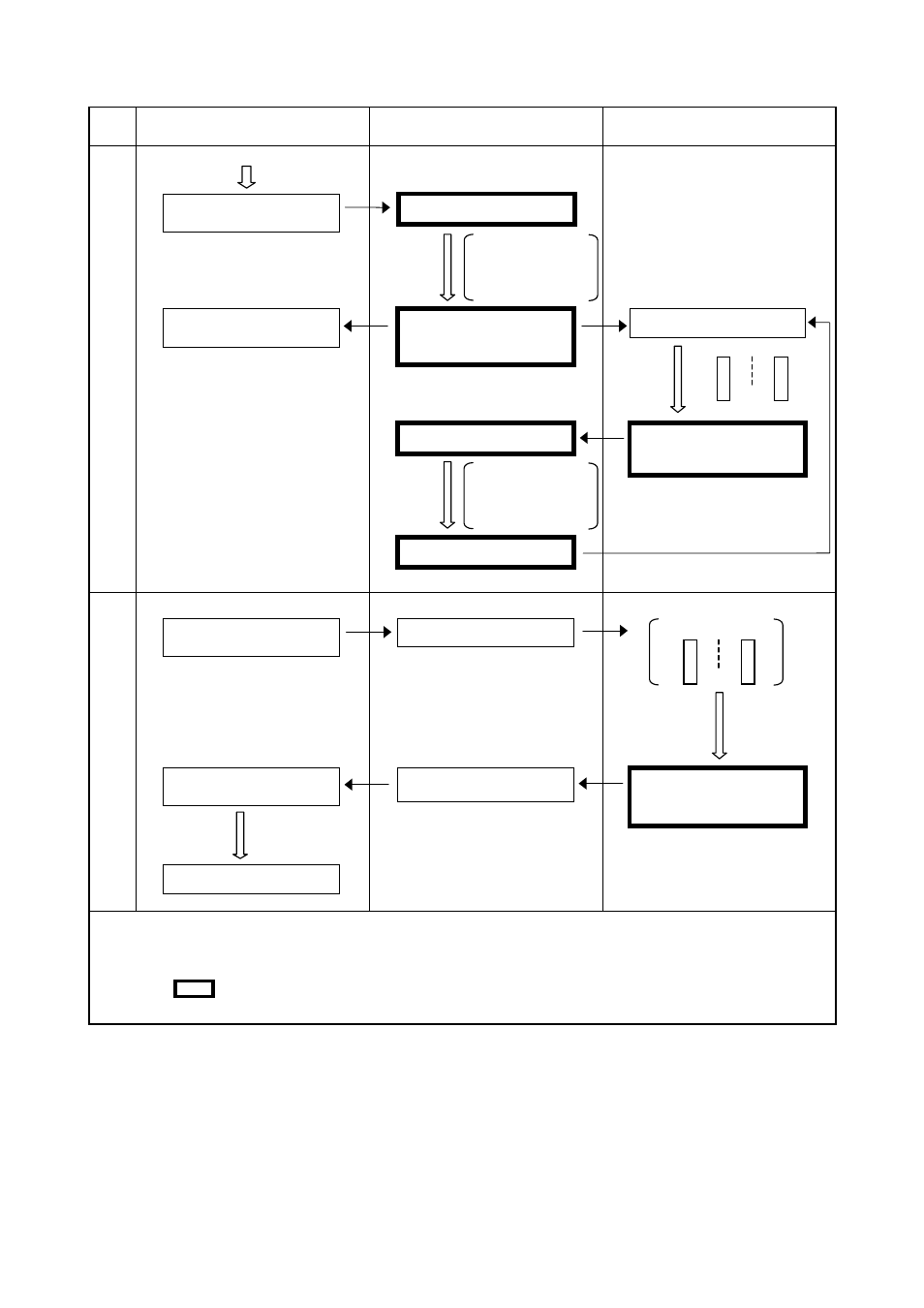
Note
S
S
S
S In data area 1, the bit to each of "motor ON, CAL execution," "external speed 100" and
"External Mode switching" will be turned ON. Refer to Chapter 5, Subsection 5.3.7
"Mode Switching (0111)".
T
T
T
T in the above figure indicates a system I/O signal, and
←
←
←
←
represents the flow of
signals.
Start and Stop Procedure and System I/O Signals-2
Regular operation
program is selected
and output to data
area 2.
Regular operation
program is selected
and output to data
area 2.
Equipment’s Automatic
Start Button ON
Executing Program
Operation Command
(Program start)
Automatic Operation
indicator lamp ON
Program No. select ON
Program start ON
Equipment power OFF
(Internal processing)
Robot-in-operation
signal OFF
Equipment’s Cycle
Stop button ON
Automatic operation
indicator lamp OFF
Program No. Select ON
Robot-in-operation
signal OFF
Repeated
Executing 1-cycle
END
END
Program start
Cycle Stop ON