Flowserve 3400IQ Digital Positioner User Manual
Page 93
3
Logix 3400IQ Digital Positioner FCD LGENIM3402-00 – 0/07
flowserve.com
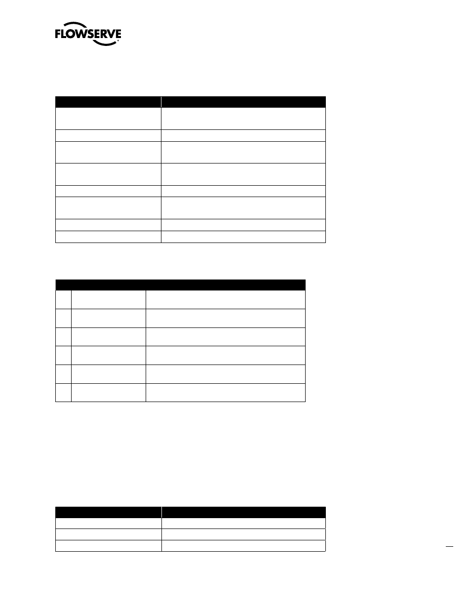
CALIBRATE_FLAGS: Each bit within this variable is a flag indicating parameters relevant to calibration.
A logic 1 indicates error is active.
Bit
Description
0
0=No error
1= Calibration time-out
1
2
0= No error
1= Position A/D converter saturated at 0% position
3
0=no error
1= Position A/D converter saturated at 100% position
4
5
0= No error
1= Position A/D converter span error
6
7
CONTROL_FLAGS: Each bit within this variable is a flag that indicates parameters relevant to position
control and calibration.
NOTE: When bit 2 is set, if bit 6 and 7 = 0, the positioner will use the custom modifiable curve. The
code will prevent both bits from being set at the same time. When bit 2 is set, if either bit 6 or 7 are
set, the corresponding default characterization curve will be used. If bit 2 = 0, the positioner will use
linear stem positioning, regardless of the value of bits 6 and 7.
FAIL_MODE: This variable is used to indicate the desired fail action of the Logix digital position should
a loss of communications occur. If this variable = 0x00, the fail action will be ‘last known position.’
Logix software prevents more than 1 bit being set at a time.
Bit
Description
0
1 = Fail to last commanded position
1
1 = Fail valve to closed (0%) position
2
1 = Fail valve to full opened (100%) position
Bit Name
Action
0
Air Action
0 = ATO
1 = ATC
2
Characterization Active
0 = Linear stem positioning
1 = Custom characterization stem positioning
3
Actuator Gains
0 = Linear actuator gains used
1 = Rotary actuator gains used
4
Model
0 = Standard positioner model (no pressure sensors)
1 = Advanced positioner model (pressure sensors)
6
Equal-percent Curve
0 = Use custom curve (user may edit)
1 = Use default equal-percent curve
7
Quick-opening Curve
0 = Use custom curve (user may edit)
1 = Use default quick-opening curve