Flowserve 3400IQ Digital Positioner User Manual
Page 111

Logix 3400IQ Digital Positioner FCD LGENIM3402-00 – 0/07
flowserve.com
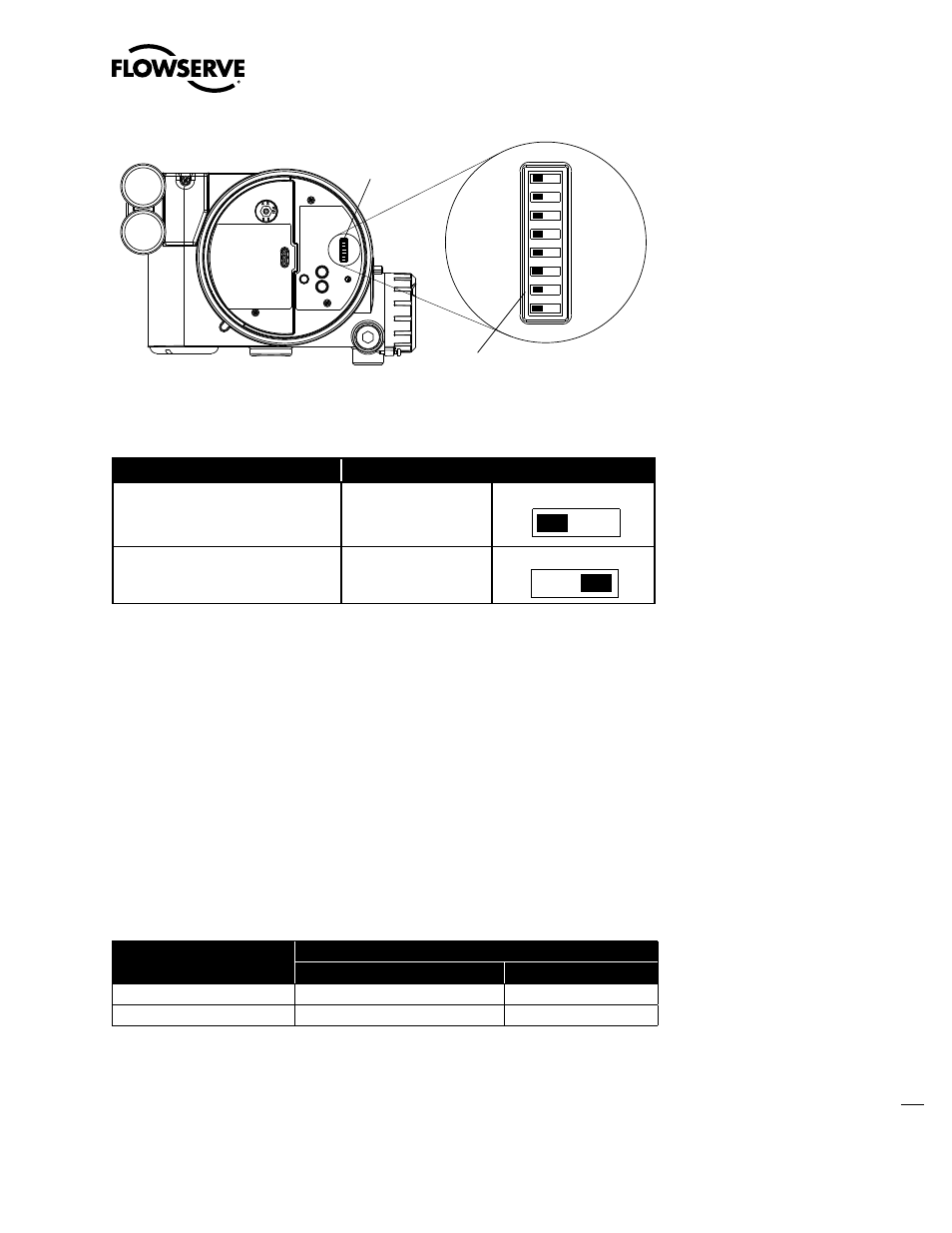
Table 10.10 Setting The Simulation Dip Switch
To
Set the Dip Switch to:
Enable read and write access to the
device’s configuration. (Factory-set
default)
Off position on the dip
switch.
Enable read only access to device’s
configuration. (Write-protect)
On position on the dip
switch.*
Enabling Simulation Mode
The SIMULATE parameter is enabled by setting the hardware simulation jumper to the Y position.
Additionally, AO block SIMULATE parameter must be set to the following values:
SIMULATE
STATUS = Good::[alarm status]:constant (suggested setting)
SIMULATE_VALUE = (supplied by user) used as the readback input to the AO block.
ENABLE_DISABLE = Active enabled
Simulation Mode Truth Table
The truth table in Table 10.11 shows the states of the simulation jumper and SIMULATE parameter to
activate the simulation mode.
Table 10.11 Simulation Mode Truth Table
When the Simulation Dip Switch on
main PCB cover is set to:
.
.. and the SIMULATE Enable_Disable is set to:
1 (Disabled)
2 (Active)
Off Position
Simulation Disabled
Simulation Disabled
On Position
Simulation Disabled
Simulation Active
Simulation Mode A simulation mode is available in the AO function block to set the value and status
of READBACK when it is necessary to override the transducer value or status.
The SIMULATE parameter contains the following elements:
SIMULATE_VALUE - Contains the value that is copied to the READBACK parameter.
SIMULATE_STATUS - Contains the status that is copied to the READBACK parameter.
•
•
DIP Switch Block
Off
On
FF Simulate
Dip Switch
Figure 10.1 Simulation Dip Switch Location on the PCB Cover
Off
On
Off
On
