Table 10.12 symptom chart – Flowserve 3400IQ Digital Positioner User Manual
Page 113
3
Logix 3400IQ Digital Positioner FCD LGENIM3402-00 – 0/07
flowserve.com
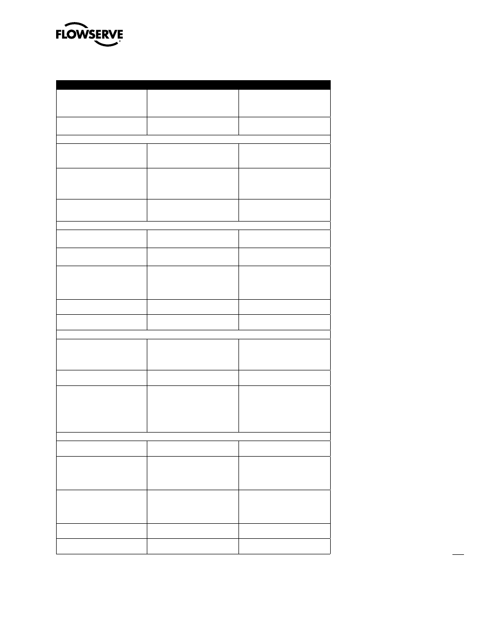
Table 10.12 Symptom Chart
Failure or Problem
Probable Cause(s)
Refer to Section(s)
Valve moves in wrong direction with no
change in input signal
1. May be tubed for wrong air action.
2. Spool stuck.
1. See Air Action in Section 6.
2. See Spool Valve instructions in Logix
3400IQ Digital Positioner IOM.
Unit does not respond to fieldbus
command.
1. Unit is not configured correctly.
1. See Theory of Operation on page 3.
2. Error occurred during calibration.
2. See Calibration in Section 9.
Calibration
LEDs blink YRYR or YRRY after a
Re-Cal operation. Valve stays in fully
open or closed position.
1. Configured for linear on a rotary
mounting.
1. See Re-Cal button Section 9.
2. Feedback linkage out of range.
LEDs blink YRRR after a Re-Cal, or
calibration operation.
1. Valve didn’t fully stroke during
calibration (low or no air supply).
1. See Re-Cal button Section 9.
2. Stuck Spool.
2. See Spool Valve instruction in Logix
3400IQ Digital Positioner IOM.
On a rotary, valve has a dead band at
the fully open or closed position.
1. Mechanical travel is not centered
within the electrical measurement range
(position sensor out of range).
1. See Linear vs. Rotary in Section 6.
Control and Tuning
Valve won’t saturate at closed position.
1. May need to enable MPC
1. See MPC in Section 8.
2. Calibration required.
Valve won’t go below or above a certain
limit.
1. Soft limits are not enabled
1. See Advanced Features in Section 10.
2. MPC is not enabled
Sticking or hunting operation of the
positioner.
1. Contamination of spool valve
assembly
1. See Air Supply Requirements on page
15. See Spool Valve in Section 10.
2. P+I setting incorrect
2. See Setting P+I Parameters in Section 10.
3. Excessive Stiction
3. Enable Hi Friction Feature
Large initial deviation; only present on
initial power-up.
1. Inner loop offset not correct.
1. See Setting P+I Parameters in Section
10.
Stem position movement is not linear
with command.
1. Custom characterization is enabled
1. See Custom Characterization in
Section 10.
Fieldbus Communication
Logix 3400IQ digital positioner will not
communicate with fieldbus.
1. Power problem.
1. See Wiring the Logix 3400IQ Digital
Positioner to a Fieldbus Network on
page 19.
2. FB card connection.
2. Verify FB protocol being used.
Configurator displays ‘Unknown’ after
it connects.
1. DD has not been loaded in the
configurator correctly.
1. Reload DD making sure Valtek
products are listed.
Erratic communications occur.
1. Maximum cable length or impedance
exceeded
1. See Wiring the Logix 3400IQ Digital
Positioner to a Fieldbus Network on
page 19.
2. Card not receiving enough power.
(Laptop batteries possibly low)
2. Refer to AGA-181 for Network
checkout procedure.
3. Interference with I.S. barrier
Alarms
Temperature alarm occurs.
1. Ambient temperature has exceeded
electronics ratings
1. See Temperature Alarm in Section 8.
Hall sensor alarm occurs.
1. Hall connector may have bad
connection
1. See Hall sensor Alarm in Section 8.
2. Sensor may be damaged
3. Low air supply pressure
3. Check air supply
Modulator current alarm occurs.
1. Modulator minimum pressure may
be too low.
1. See Modulator current Alarm in
Section 8.
2. Clogged orifice
3. Bad cable connection
EEPROM checksum alarm occurs.
1. Error when reading non-volatile
memory storage
1. See EEPROM checksum Alarm in
Section 8.
Multiple internal flags occur.
1. Bad micro-controller on main PCB
assembly.