St3000 ff, Fieldbus logix 3400iq dp, Valve – Flowserve 3400IQ Digital Positioner User Manual
Page 14
Logix 3400IQ Digital Positioner FCD LGENIM3402-00 – 0/07
4
In addition to providing the Fieldbus Interface the Logix 3400IQ digital positioner can also perform
loop control functions. In conjunction with other FOUNDATION fieldbus compliant devices, its func-
tion block set allows the formation of an extensive set of basic control applications.
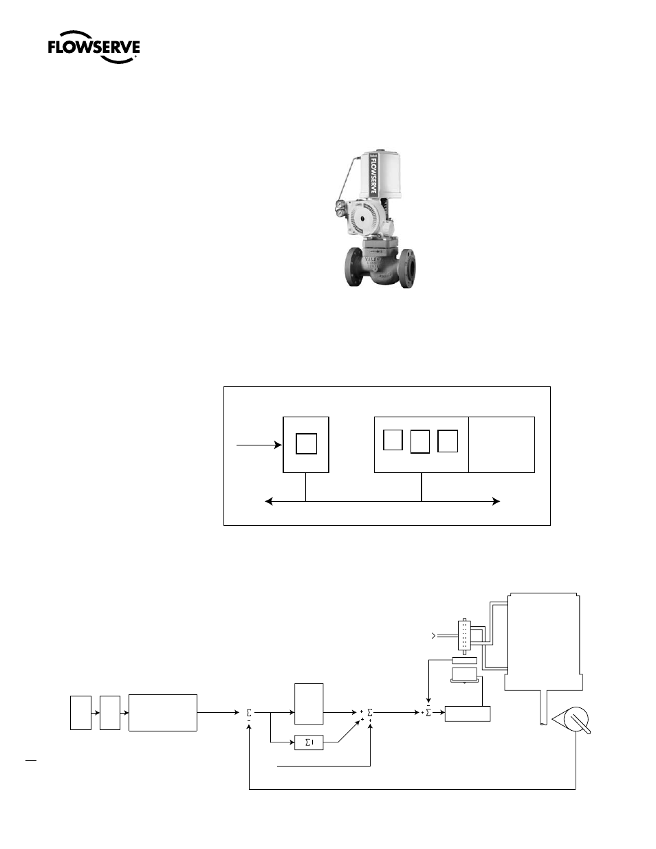
Figure 1.1 Fieldbus Positioner (Logix 3400IQ Digital Positioner)
The Logix 3400IQ digital positioner in conjunction with any valve will, in essence, form a Fieldbus
valve. When configured in conjunction with an Honeywell ST3000 fieldbus transmitter (for example)
a complete control loop can be configured. Figure 1.2 shows a block diagram of the Logix 3400IQ
digital positioner digital positioner operating with other instrument
Figure 1.2 Functional Block Diagram of Logix 3400IQ Digital Positioner
0perating with other instruments
Theory of Operation
Figure 1.3 shows the basic positioning block diagram for the Logix 3400IQ digital positioner.
Figure 1.3 Digital Positioner Block Diagram
ST3000 FF
AI
Fieldbus
Logix 3400IQ DP
PID
AO
XD
Valve
Stem
Position
Sensor
Tubed ATO
Sensor
Air Supply
Piezo Valve
Voltage
Inner Loop
Spool Control
Inner-Loop
Hall Sensor
Output
D/A Output
Percentage
Control
Algorithm
Deviation
Position
P
max
P
min
G
mult
Integration Summer
Inner Loop Offset
XD
AO
+
Control
Command
(CMD_USED)
(GAIN_UPPER)
(HALL_SENSOR)
(GAIN_LOWER)
(GAIN_MULTI)
(IL_OFFSET)
Linear Mode
Characterization
Soft Limits
MPC