12 characterization procedure – Flowserve 3400IQ Digital Positioner User Manual
Page 119
Logix 3400IQ Digital Positioner FCD LGENIM3402-00 – 0/07
flowserve.com
Table 10.15 Transducer Block Characterization Parameters
Parameter
Description
Value — Meaning
Comments
MODE_BLK
The operating mode of the
transducer block
Permitted Modes: Auto
- Auto (target mode) OOS
- Out of Service
The transducer block
must be out-of-service
before the user can edit or
change characterization.
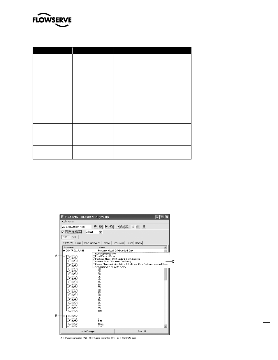
CONTROL_FLAGS
Byte values which select
positioner operation fea-
tures
1 Quick Opening Curve* Loads factory defined QO
curve as custom curve.
2 Equal Percent Curve
Loads factory defined
equal percent curve as
custom curve.
4 Positioner Model
5 ActuatorStyle
6 Custom Characteriza-
tion Active
Activates custom curve. If
Off, response is Linear.
8 Air Action
CURVEX
Numeric X value array for
custom point. (1x21 array
points)
X-axis value for custom
stroke characterization
point. Range -10 to 110
Pair each X-value with
corresponding Y-value to
define the desired point.
Values must be in ascen-
ding (or equal) order.
CURVEY
Numeric Y value array for
custom point. (1x21 array
points)
Y-axis value for custom
stroke characterization
point. Range -10 to 110
* Must not be selected if a custom curve is to be created or edited.
10.12 Characterization Procedure
The following procedure outlines the basic way setting up a custom stroke characterization takes
place.