Table 8.9 honeywell pid parameters – Flowserve 3400IQ Digital Positioner User Manual
Page 60
Logix 3400IQ Digital Positioner FCD LGENIM3402-00 – 0/07
0
Table 8.9 Honeywell PID Parameters
Parameter Name
Description/Parameter Contents
ERROR_ABS
Absolute value of the difference between PV and working set-point. (Read-
only parameter.)
WSP
Working set-point. This is the set-point value after absolute and rate limits
have been applied. Deviation alarms are computed on this value. (Read-
only parameter.)
BLOCK_TEST
An internal Honeywell test parameter.
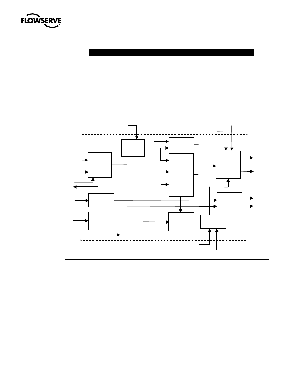
PID Block Diagram
Figure 8.4 is a block diagram showing the key components of the PID control function block.
Figure 8.4 PID Control Block
PID Block Description
PID control function block is an algorithm that produces an output signal in response to the
measured variable and the set-point. The PID function block allows the user to choose either a
standard PID control equation (Ideal) or a robust PID equation defined by Honeywell. This selection is
defined in the PID_FORM parameter.
The output has three terms: Proportional, Integral and Derivative. The output is adjusted by tuning
constants. Three tuning constants are contained in the ideal PID equation.
The robust PID uses four tuning constants.
1. GAIN is the tuning constant of the Proportional term.
2. RESET is the tuning constant of the Integral term.
Setpoint
SP_RATE_DN
SP_RATE_UP
SP HI LIM
SP_LO_LM
SHED_OPT
Mode Select
BKCAL_OUT
GAIN
RESET
RATE
BAL_TIME
PID Control
CAS_IN
RCAS_IN
IN
RCAS_OUT
BKCAL_IN
Output
OUT_ HI_LIM
OUT_LO_ LIM
BAL_T IME
OUT
TRK_SCALE
Output Track
TRK_IN_D
TRK_VAL
SP
PV_FTIME
PV Filter
PV
BYPASS
Bypass
HI/LO
DEV
Alarm
FF_SCALE
FF_GAIN
Feed Forward
ROUT_IN
ROUT_OUT
WSP
Backward
Path Outputs
Target &
Permitted
Mode
Actual &
Normal
Mode
FF_VAL
PID_FORM
ALGO_TYPE
OUT_LAG
GAIN_NLIN
GAIN_COMP
ERROR_ABS
BKCAL_HYS