9 configuration tasks – Flowserve 3400IQ Digital Positioner User Manual
Page 37
37
Logix 3400IQ Digital Positioner FCD LGENIM3402-00 – 0/07
flowserve.com
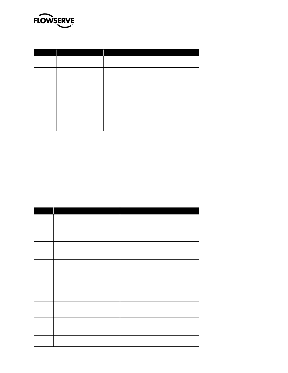
Table 6.4 Logix 3400IQ Digital Positioner Identification
Step
View Parameter
Verify
1
RS.DEV_TYPE
The Logix 3400IQ digital positioner is the proper device type:
For the Logix 3400IQ digital positioner, the value is = 0x0202
2
RS.REVISION_ARRAY
The revision number of the:
REVISION_ARRAY =
REVISION_ARRAY =
REVISION_ARRAY =
Fieldbus board boot code (0x204)
Fieldbus board boot code (Not critical)
Positioner board firmware (0x0024 or 0x0025)
NOTE: These numbers are helpful when troubleshooting the device.
3
Physical Device Tag
NOTE: The device tag name is
not contained in a parameter.
It can be set and viewed
using the fieldbus device
configurator application.
The physical device tag is correct.
6.9 Configuration Tasks
Device Configuration Procedure Overview
A typical device configuration consists of the following tasks listed in Table 6.5 using the NI-FBUS
Configurator application. Details on using the configurator application are found in the NI-FBUS
Configurator user manual supplied with the application software.
This procedure assumes that the hardware installation of the Logix 3400IQ digital positioner is
complete and the Logix 3400IQ digital positioner is powered up.
Table 6.5 Logix 3400IQ Digital Positioner Configuration Task List
Task
Procedure
Result
1
Start the fieldbus process application
Scans the fieldbus network and provides a listing
of all active fieldbus devices on the network or
selected link.
2
Start the fieldbus configurator application
Configurator windows are displayed on screen
listing the active fieldbus devices.
3
Select a fieldbus device for configuration
4
Change the device and block tags, if
desired.
Any unassigned tags are given a default tag name
by the configurator.
5
Select/add/edit function blocks to create a
function block application process.
NOTE: Configure block objects in the
following order:
1. Resource block
2. Transducer block
3. Analog Output block
4. PID block
Shows a representation of function blocks in the
graphical interface window.
6
Connect (or wire) function blocks to
define process loops.
Linkages between function block inputs and outputs
are created by using wiring tools. Pre-configured
templates can also be used.
7
Change block parameters, if necessary.
Parameters changed for the process requirements.
8
Configure trends and alarms
Trending and alarms configured according to the
process requirements.
9
Adjust the block execution schedule.
The function block execution schedule changed
according to the process requirements.