Flowserve 3400IQ Digital Positioner User Manual
Page 35
3
Logix 3400IQ Digital Positioner FCD LGENIM3402-00 – 0/07
flowserve.com
3.
ATTENTION: Using a ground strap or ionizer is highly recommended when handling the
electronics module, because electrostatic discharges can damage certain circuit
components.
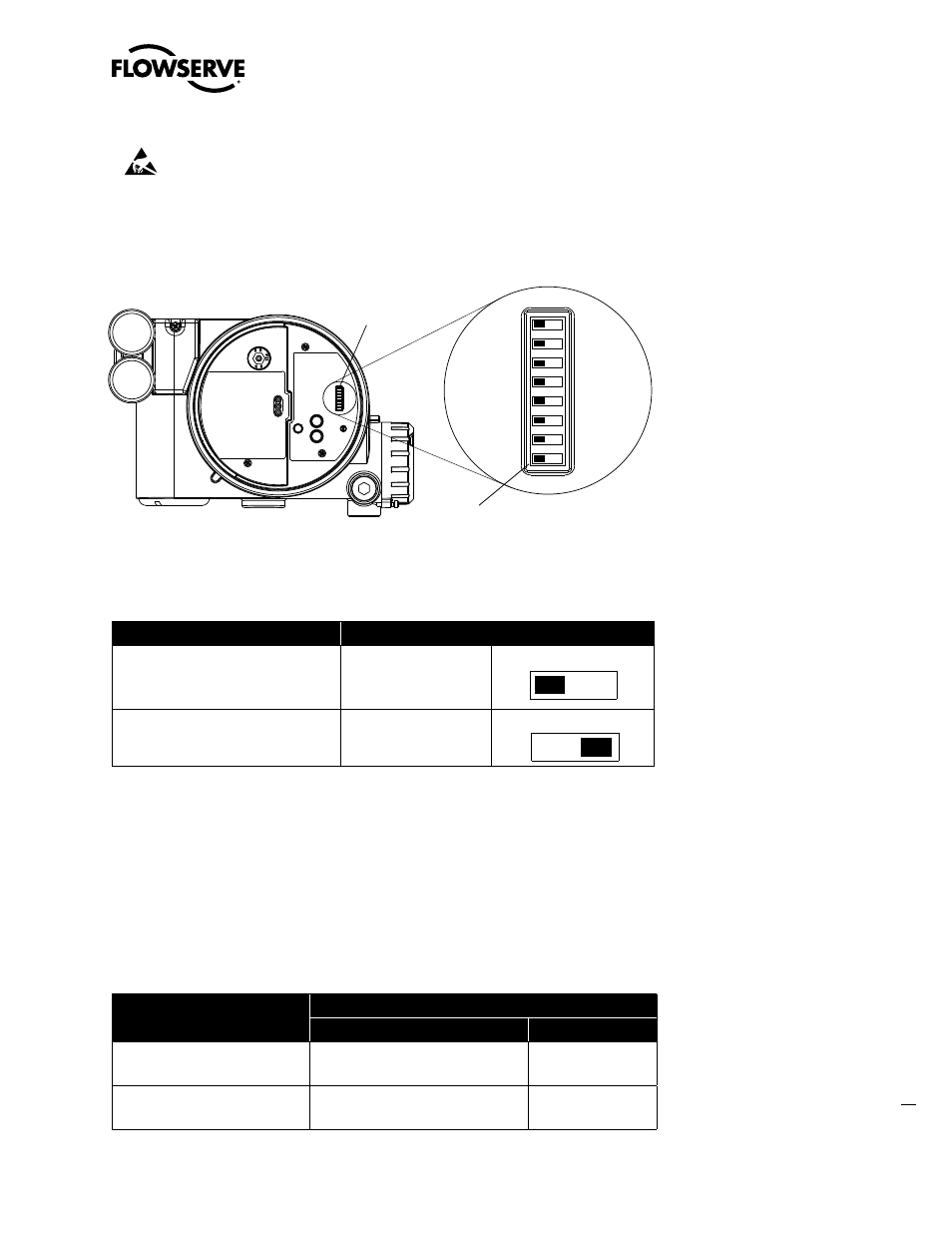
4. Locate the dip switch on the main electronic boards in the housing.
5. Set write-protect dip switch to the appropriate position on the electronics board. See Figure 6.1
and Table 6.1.
6. Replace the cover and lock the locking screw.
Figure 6.1 Write-protect Jumper Location on Controller Board
Table 6.1 Write Protect dip switch Settings
To
Set the Dip Switch to:
Enable read and write access to the
device’s configuration. (Factory-set
default)
Off position on the dip
switch.
Enable read only access to device’s
configuration. (Write-protect)
On position on the dip
switch.*
* FEATURE_SEL parameter must also be set accordingly to enable write protect. (Set FEATURE_SEL
= Hard W Lock in the Resource Block)
Enabling Write Protect Feature
The write-protect feature is activated only when the HARD_W_LOCK option is set in the
FEATURE_SEL parameter. Once the bit is set and W/R jumper is in R position, the device will remain
write-protected until the device is powered down and the jumper is placed in the W position. See
Table 6.2 for truth table.
Table 6.2 Write-protect Feature Truth Table
When the Write-protect dip switch
main PCB cover is set to:
... and the FEATURE_SEL HARD_W_LOCK option is set to:
0 (No)
1 (Yes)
Off position
Write-protect Disabled
Write Protect
Disabled
On position
Write-protect Disabled
Write Protect
Enabled
DIP Switch Block
FF Write Protect
Dip Switch
Off
On
Off
On
Off
On