3 mbt-5000 ground and power connections, 1 chassis ground interface, 2 alternating current (ac) power interfaces – Comtech EF Data MBT-5000 User Manual
Page 42
MBT-5000 L-Band Up/Down Converter System
MN-MBT5000
Rear Panel Connections
Revision 4
3–10
3.3
MBT-5000 Ground and Power Connections
3.3.1
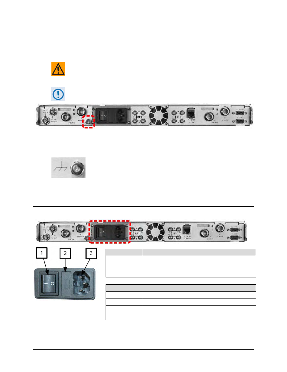
Chassis Ground Interface
CAUTION – PROPER GROUNDING PROTECTION IS REQUIRED. The equipment must be
connected to the protective earth connection at all times. It is therefore imperative
that the unit is properly grounded, using the ground stud provided on the unit rear
panel, during installation, configuration, and operation.
The AC power interface provides the safety ground.
(Optional Redundancy Unit w/Standard AC Power Shown)
Figure 3-4. MBT-5000 Chassis – Common Ground Interface
This #10-32 stud is located at a common chassis location to the left-hand side
of the standard AC, optional dual AC, or optional DC power module (Figure
3-4). Use this stud for connecting a common chassis ground among
equipment.
3.3.2
Alternating Current (AC) Power Interfaces
3.3.2.1 Standard 90-260V Alternating Current (AC) Power Interface
Figure 3-5. MBT-5000 Standard AC Power Interface
Feature
Description
1
On / Off Switch
2
Press-fit Fuse Holder
3
IEC Three-prong Connector
AC Power Specifications
Input Power
75W maximum, less than 65W typical
Input Voltage
90 to 260V AC
Connector Type IEC-320
Fuse Protection
Line and neutral fusing – (2X) T2.0A 20mm slow-blow fuses