Channel controls, Trigger controls, Channel controls 4.2.8. trigger controls – Dataman 520 Series User Manual
Page 49
DATAMAN oscilloscope
User’s Guide
- time between vertical cursors
- frequency between vertical cursors
WARNING: If the information about the time between trigger event and vertical
cursor 1 has to be accurate (error smaller than 10ns), it is necessary to make the
following correction: measure the time between the trigger event mark and the
real trigger event and use this value to correct the information.
If the sampling mode is activated, the icon is displayed with two rectangles
reflecting the amount of samples acquired (left rectangle represents channel A, right
one represents channel B):
red – less than 50% samples are acquired
yellow – more than 50% but less than 100% samples are acquired
green –100% samples are acquired
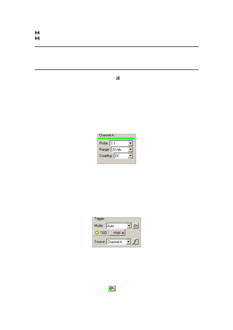
4.2.7. Channel controls
The channel controls are located in the bottom of the main window.
Fig. 4.2.7.1. – Channel controls
Click „Probe“ combobox to select the probe attenuation on the appropriate channel.
Click „Range“ combobox to select the range on the appropriate channel.
Click „Coupling“ combobox to select the coupling on the appropriate channel.
4.2.8. Trigger controls
The trigger controls are located in the bottom of the main window.
Fig. 4.2.8.1. – Trigger controls
Click „Mode“ combobox to select the trigger mode. The following four trigger modes
are available:
„Normal“ – Produces a sweep only when the trigger signal meets the threshold level
and slope criteria. If the “Enable flag in normal trigger mode (starts acquisition)” is
enabled in the options, clicking on the
button starts data acqusition with no regard
to the trigger.
- 49 -