Dataman 520 Series User Manual
Page 19
DATAMAN oscilloscope
User’s Guide
AMP
AMP
DA
A
B
KB
KA
ta
tb
PTSS
STSS
E
A B E
A B E
DF
DF
EC
EC
trg
TDL
MS
Primary level
Secondary level
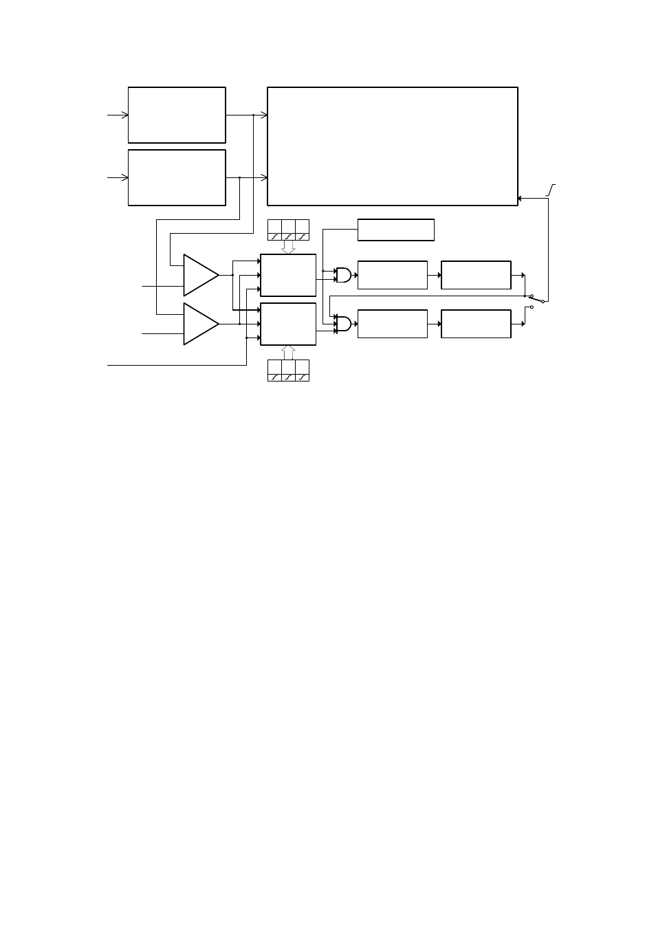
Fig. 2.2.2.1. – Block schematics of trigger circuits
Data for trigger circuits come either from Channel A, Channel B or from the external
trigger input (E). The comparators KA an KB produce binary signals for Primary
Trigger Source Selector (PTSS) and Secondary Trigger Source Selector (STSS) while
the threshold of each comparator (ta, tb) can be set to any value in the vertical range.
If the actual output voltage of the channel is higher then the actual threshold the
output of the comparator is set to 1 (TRUE). If it is lower than the threshold, the
output will be 0 (FALSE). The Trigger Source Selectors for each triggering level are
independent. It is possible to select the source of triggering signal for each level
independently. In addition to source selection, the PTSS and STSS can invert any of
the input signal The trigger event is generated with respect to the change of the
selector (PTSS, STSS) output signal from 0 (FALSE) to 1 (TRUE). A constant level
of the signal cannot start the measurement. In the case that only one of the signals is
selected, the trigger event is generated corresponding to the polarity, which is
symbolically presented by the direction of change of the signal. (0 to 1 means no
inversion). When there are several inputs selected, the selector makes a logical
addition (OR) of all of the selected inputs. Before adding the signals together, ones
are adjusted with respect to the polarity settings. A trigger event is generated only
when the change of the result of the logical addition occurred from 0 to 1 (FALSE to
TRUE). Logical values of the signals in the input of logical adder (OR) from which
the trigger event is generated are created on the basis of following rules: value 0
(FALSE) is the value that selector input signal should have before the valid trigger
event. 1 (TRUE) is the value that this signal will have after the valid trigger event. For
example, if triggering from Channel A is set to the trailing edge, then the output
voltage of the channel is higher than the threshold voltage, the consequent value on
the adder input will be 0 (FALSE). An inverse situation will be taken as 1 (TRUE).
Note that when using logical addition, all values must be 0 (FALSE) in order for the
result to be 0 (FALSE). It is relatively easy to find out which are the valid trigger
- 19 -