Digital shielding (dsh), Trigger circuits, Digital shielding (dsh) 2.1.2. trigger circuits – Dataman 520 Series User Manual
Page 14
DATAMAN oscilloscope
User’s Guide
prevent the occurrence of a trigger event after the start of data acquisition. This
feature allows you to acquire the proper amount of data before the trigger.
Each measuring channel of the DATAMAN 570 series oscilloscopes has its own AD
converter. No channel multiplexing is used for dual channel operation.
2.1.1. Digital Shielding (DSH)
Digital Shielding removes interference asynchronous with the measured signal, and it
does not affect the frequency characteristics of the measured waveform. The only
negative effect of DSH is a longer time period of waveform stabilization. It is,
however, very simple to turn the DSH off using the on-screen controls. The DSH
efficiency level corresponds to the DSH level factor that can be set to any value from
2 to 64. The higher the level you choose, the longer it takes to stabilize.
2.1.2. Trigger circuits
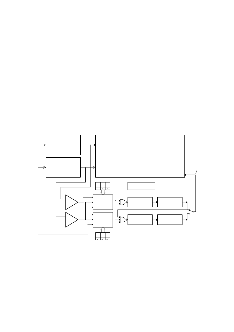
The block schematics of the dual level trigger circuits are shown in figure 2.1.2.1.
AMP
AMP
DA
A
B
KB
KA
ta
tb
PTSS
STSS
E
A B E
A B E
DF
DF
EC
EC
trg
TDL
MS
Primary level
Secondary level
Fig. 2.1.2.1. – Block schematics of trigger circuits
Data for trigger circuits come either from Channel A, Channel B or from external
trigger input (E). The comparators KA an KB produce binary signals for Primary
Trigger Source Selector (PTSS) and Secondary Trigger Source Selector (STSS) while
the threshold of each comparator (ta, tb) can be set to any value in the vertical range.
If the actual output voltage of the channel is higher, then the actual threshold the
output of comparator is set to 1 (TRUE). If it is lower than the threshold, the output
will be 0 (FALSE). The Trigger Source Selectors for each triggering level are
independent. It is possible to select the source of the triggering signal for each level
independently. In addition to source selection, the PTSS and STSS can invert any of
- 14 -