Channel information – Dataman 520 Series User Manual
Page 42
DATAMAN oscilloscope
User’s Guide
Channel A controls are located in the left, channel B controls are located in the right.
“1:1”, “1:10”, “1:100” or “1:1000” – probe attenuation ratio
WARNING: Selection of improper probe attenuation ratio may result in
incorrect information about voltages.
Click
or
to select coupling. Click
to ground input.
If the external attenuation is enabled in the options the external attenuation controls
are available in the top of the panel.
Fig. 4.1.12.2. – External attenuation controls
External attenuation controls allow you to measure the voltage on the divider where
the software automatically calculates voltage on the divider input.
WARNING: In case you are using 1:10 probe, don’t use external attenuation
controls to perform transformation. Please always use above mentioned controls
to set the probe attenuation.
Click the button to open the window where you can select the divider attenuation.
Fig. 4.1.12.3. – Selecting external attenuation
Click „1:1“ button to set 1:1 ratio automatically.
Enter the value into the edit box to select the ratio. It is possible to enter the value as
the real number (such as „0.5“) or as the ratio (for example „1:2“).
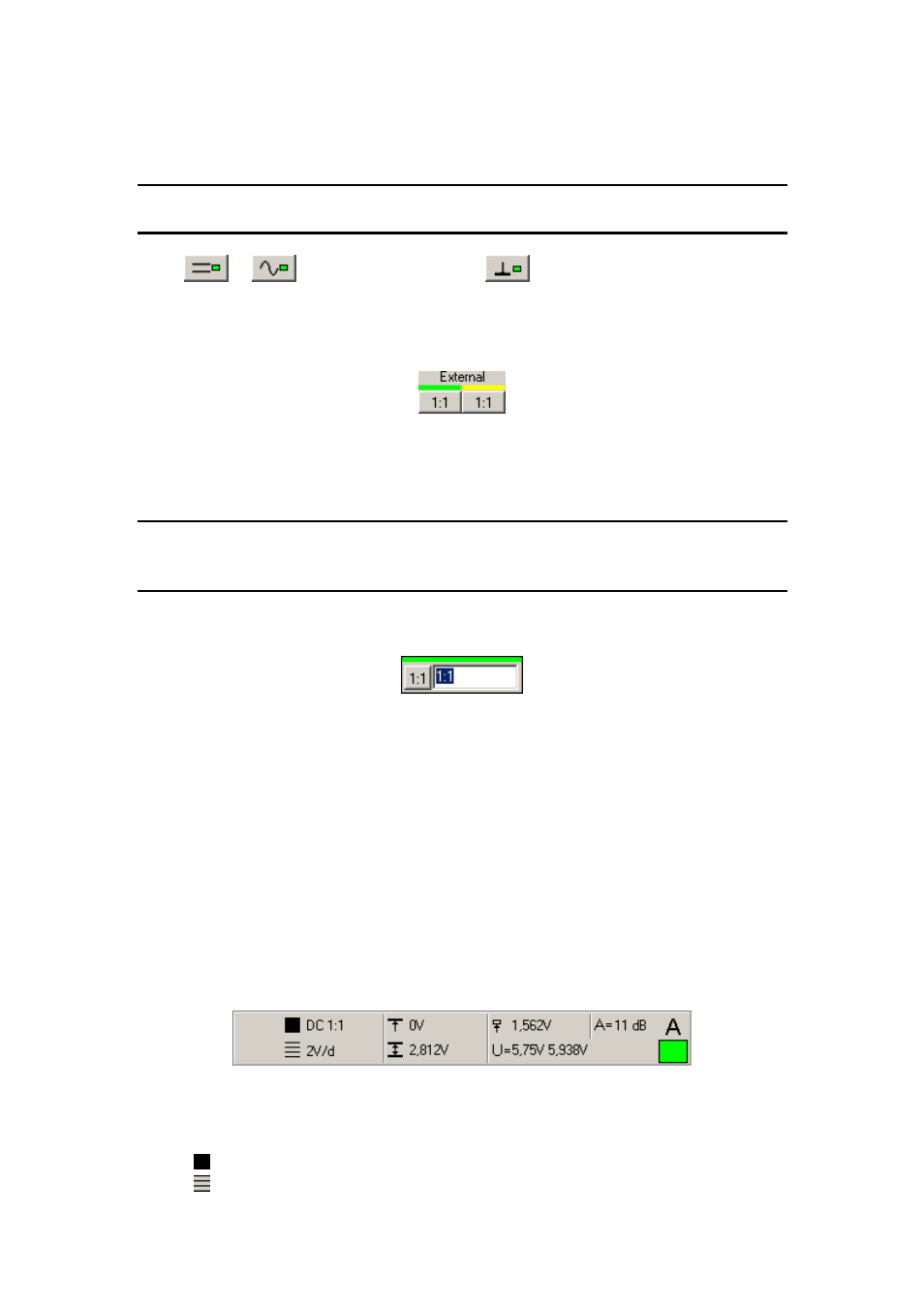
4.1.13. Channel information
The channel information is displayed in the top of the main window.
Channel A information is located in the left, channel B information is located in the
right.
Fig. 4.1.13.1. – Channel information
The following information is displayed:
- information about coupling and probe attenuation ratio
- range
- 42 -