Reznor YDSA Unit Installation Manual User Manual
Page 53
Form I-Y, P/N 273646R6, Page 53
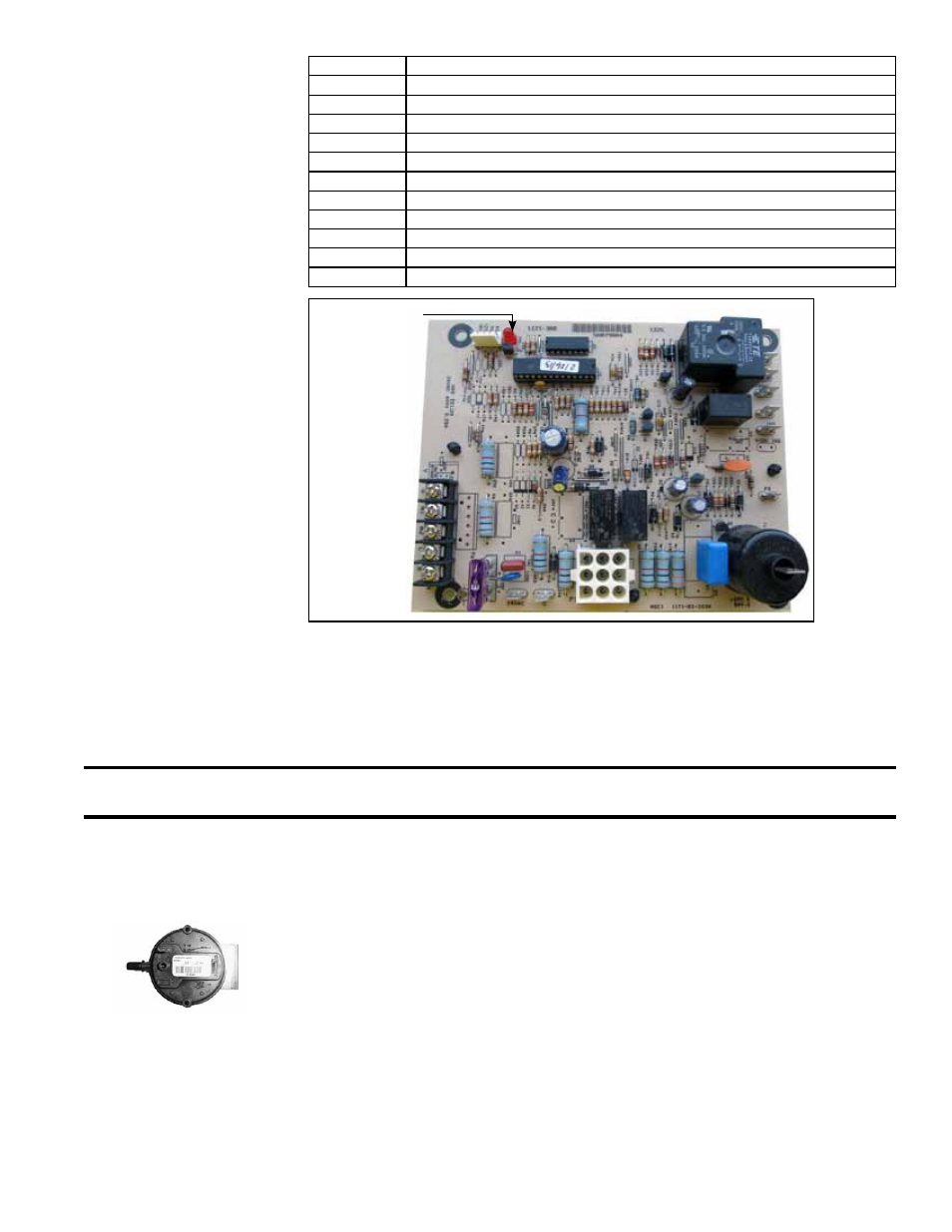
DSI Control Module
LED Flash Codes
Flash Code Description
Fast Flash Normal operation
Steady OFF No power, blown fuse, or defective board
1
Low pressure switch stuck open
2
Low pressure switch stuck closed
3
High pressure switch stuck open
4
High pressure switch stuck closed
5
Limit switch open
6
Ignition lockout (failed ignition)
7
Too many (5) limit switch losses
8
Too many (5) flame losses
9
Too many (3) high pressure switch losses during one call for heat
All gas furnaces are equipped with a temperature activated auto reset limit control.
Depending on size, the control is factory set at either 200°F or 250°F and is non-
adjustable. If the setpoint is reached, the limit control will interrupt the electric supply
to the gas valve. This safety device provides protection in the case of a lack of airflow
due to dirty filters or a restriction at the inlet or outlet.
The limit control switch is mounted on the side of the heat exchanger (See location in
FIGURE 23, page 39 or FIGURE 24A, page 43).
High Temperature
Limit Control
FIGURE 26 - DSI
Control Module
LED Light
Combustion Air and
Venting
Combustion Air Proving Switch
The combustion air proving switch is a pressure sensitive switch that monitors air pres-
sure to ensure that proper combustion air is available. The switch is single pole/single
throw with the normally open contacts closing when the proper airflow is sensed in the
system.
The gas heat section is power vented. Presence of combustion air pressure is moni-
tored by a combustion air proving switch located in the heat section.
On start-up when the heater is cold, the sensing pressure is at the most negative
level, and as the heater and flue system warm up, the sensing pressure becomes less
negative. After the system has reached equilibrium (about 20 minutes), the sensing
pressure levels off.
If a restriction or excessive flue length or turns cause the sensing pressure to be out-
side the switch setpoint, the pressure switch will function to shut off the main burners.
The main burners will remain off until the system has cooled and/or the flue system
resistance is reduced. The table below lists the approximate water column negative
pressure readings and switch set points for sea level operating conditions.
CAUTION: The auto reset limit control will continue to shut down the heat section until the
cause is corrected. Never bypass the limit control; hazardous conditions could result.