Potter PFC-6030 User Manual
Page 39
3-33
PFC-6030 • 5403595 • Rev C • 2/13
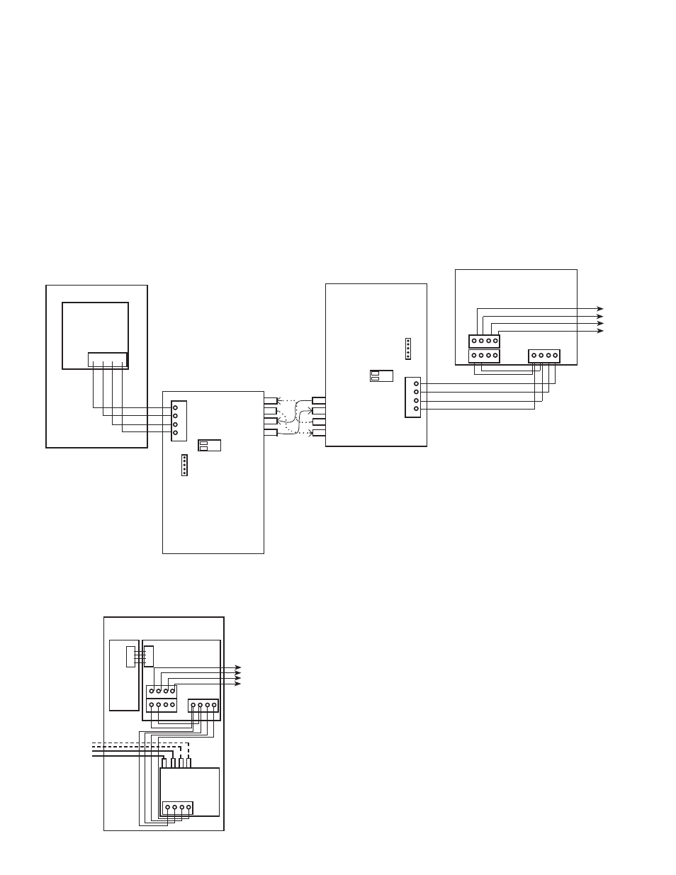
FIB-1000 Wiring
FIB-1000s are installed in pairs. (Please refer to Diagrams #1 & 2 shown below to properly wire the two FIB-1000s.) The first
FIB-1000, referred to as "FIB-1000 (A)" below can be installed in any of the compatible fire alarm enclosures, or the FIB-
1000RM. It is connected via the 4-wire P-Link connection. Set S2 on FIB-1000 (A) to the "OFF" position, which provides an
outgoing fiber option connection. That fiber optic connection can be connected as Class A or Class B to the second FIB-1000,
referred to as "FIB-1000 (B)" below.
The second FIB-1000 (B) is installed in a PSN-1000E (shown in Diagram #2 below). Set S2 on FIB-1000 (B) to the "ON"
position. It then provides an outgoing P-Link connection. Connect the 4-wire P-Link on the FIB-1000 (B) to the P-Link
connection on the PSN-1000E.
To power the FIB-1000 (B), connect the 24VDC "+" and "-" terminals on PSN-1000E (shown in Diagram #2 below) to the
isolated P -Link 24 VDC "+" and "-" terminals. The PSN-1000E's isolated P-Link can now be used to connect any other
P-Link appliance, including the RA-1000, LeD-16, and PSN-1000/PSN-1000e.
Diagram #1: FIB-1000 Wiring Diagram Showing Detail
Figure 45.
Diagram #2: FIB-1000 Wiring Diagram Shown Installed in PSN-1000E Cabinet
Figure 46.
Master Panel or PSN1000E
P-LINK
PSN-1000
B
A
+
-
B
A
+
-
To Additional
P-Link Devices
B
A
+
-
S1
S2
ON
OFF
-
+
A
B
S2
S1
ON
OFF
FIB-1000 (A)
Upstream FIB
S2 = OFF
S2 =
OFF
FIB-1000 (B)
Downstream FIB
S2 = ON
ON
R x 2
T x 2
R x 1
T x 1
T x 1
R x 1
T x 2
R x 2
Fiber Optic
Cable
OUT
IN
DWG #608-25B
PSN-1000E
B
A
+
-
B
A
+
-
T1
R1
R2 T2
B
A
+
-
FIB-1000 (B)
To Additional
P-Link Devices
Fiber In
DWG #608-25A