Isolator device load calculation – Potter PFC-6030 User Manual
Page 16
2-10
PFC-6030 • 5403595 • Rev C • 2/13
Isolator Device Load Calculation
This section covers the distinction between an addressable sensor and an isolator to correctly calculate the total SLC device load.
A device uses an address and consumes power. Whereas, an isolator does not use an address, but does consume power.
The following scenarios explain how to calculate the current device load based on the SLC configuration.
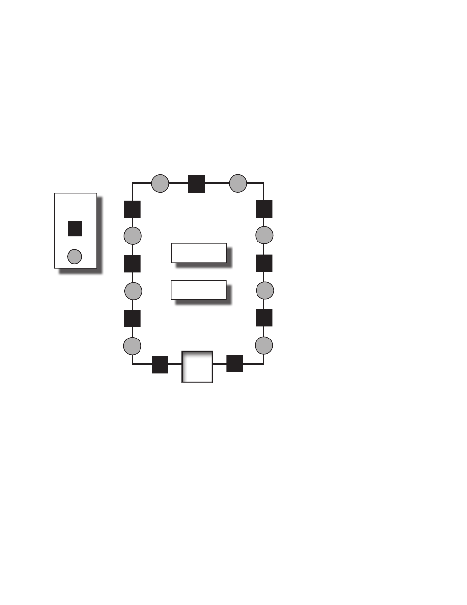
Scenario 1: Class A Loop – Isolated Devices Configuration
In this configuration, each sensor and isolator device / module counts as one (1) when calculating the total device load.
Formula: Total # addressable devices + Total # isolators = Total power unit allocations (or device load)
Example of a Class A Loop – Isolated Branches
Figure 3.
Configuration Summary:
Total addressable devices = 8 (sensors only) out of 30 possible addressable points.
Total device load = 17 (calculated as follows: 8 sensors + 9 isolators) out of 127 power unit allocations.
Example: If a configuration uses 30 sensors, up to 97 isolators may be supported.
Solution: 127 - 30 = 97
LEGEND:
ISO Module/
Device
Sensor
PANEL
Total addressable
devices = 8
Total isolators = 9
DWG # 593-4