Potter PFC-6030 User Manual
Page 22
3-16
PFC-6030 • 5403595 • Rev C • 2/13
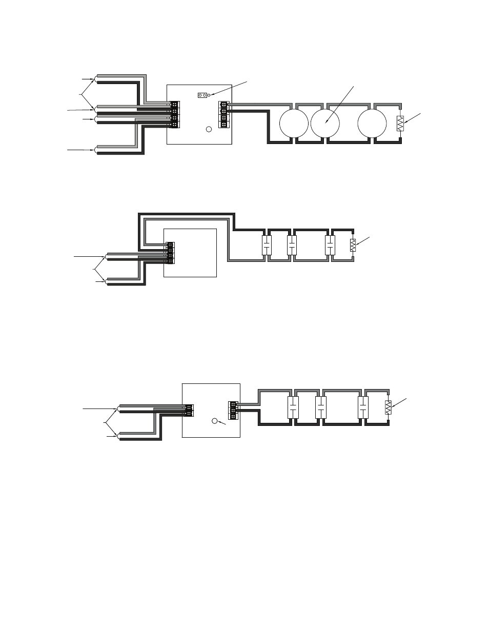
Conventional Initiating Zones (CIZM-4) Class B
CIZM-4, Class B
Figure 12.
Conventional Initiating Zone Module
Model No. CIZM-4
Note: The resistance of external wiring shall be less that 100Ω.
The capacitance of external wiring shall be less than 1 micro farads.
From FACP or
Previous Module
To Next Module
From FACP or
Previous Module
To Next Module
24-
24+
S-
S+
A-
A+
SLC Loop
LED
JP1
Conventional
Detector
5.1KΩ 1/2W
EOLR
_
+
_
+
_
+
B-
B+
Select Style B
DWG #593-12
Miniature Contact Module (MCM)
Refer to the figure shown below for a MCM wiring example.
MCM Wiring Example
Figure 13.
COM
NO
S-
S+
5.1KΩ 1/2W EOLR
SLC Loop
To Next Module
From FACP or Previous Module
Note: The resistance of external wiring shall be less that 100Ω.
The capacitance of external wiring shall be less than 1 micro farads.
Mini Contact Module
Model No. MCM
DWG #593-13
Note: If MCM is located in an electrical box, it should be secured using crew tabs or other method to prevent movement.
Single Contact Module – 4 inch Mount (SCM-4)
Refer to the figure shown below for a SCM-4 wiring example.
SCM-4 Wiring Example
Figure 14.
COM
NO
S-
S+
SLC Loop
To Next Module
From FACP or Previous Module
Single Contact Module
Model No. SCM-4
5.1KΩ 1/2W EOLR
Note: The resistance of external wiring shall be less that 100Ω.
The capacitance of external wiring shall be less than 1 micro farads.
Z
LED
DWG #593-14