Relay board installation (rly-5) – Potter PFC-6030 User Manual
Page 36
3-30
PFC-6030 • 5403595 • Rev C • 2/13
Setting Addresses
The DRv-50's address is set by dip switch S1, which is located on the back of the board. The address must be set in the range
of one to thirty-one (1–31) to be recognized by the panel. (Refer to the "P-Link Addresses" table shown earlier in this section for
DIP switch programming.)
DRV-50's Back Panel View Showing Dip Switch Location
Figure 37.
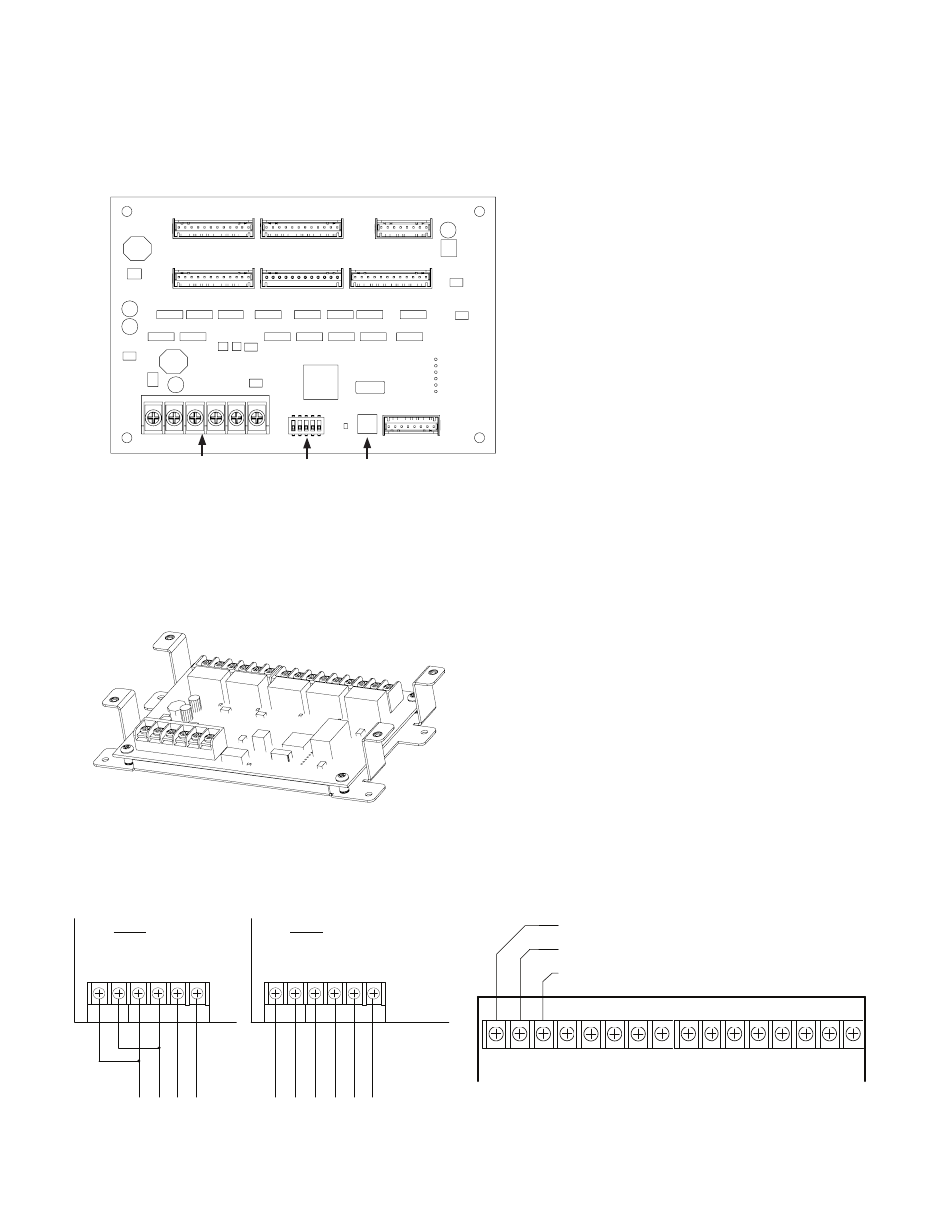
Relay Board Installation (RLY-5)
This panel supports up to thirty-one (31) RLY-5s. The RLY-5 (Relay Board) module is controlled over the 4-wire P-Link
connection. The RLY-5 mounts in a mounting bracket as shown below, and then installed into the panel cabinet, or in either of the
Ae-8 or Ae-14 accessory cabinets.
RLY-5 Board Showing Mounting Bracket
Figure 38.
The RLY-5 higher current required for the relay outputs can be provided by the panel, or from an auxiliary power source as shown
below. The auxiliary power can be any 24vDC source, and is fully supervised.
RLY-5 Wiring to Control Panel or Auxiliary Power Supply Examples & RLY-5 Showing Normally Open/Normally Closed Contacts
Figure 39.
DWG #608-10
DWG #608-22
Dip Switch
P-Link
Connections
S1
RLY PWR P -Link
-
+ -
+ A B
P-Link from
control panel
Example:
Powered by
control panel
-Link
-
+ -
+ A B
P-Link from
control panel
Example:
Powered by
aux supply
Power from
auxiliary
supply
RLY PWR P
DWG #608-6
NC (Normally Closed)
C (Common)
NO (Normally Open)
NC C NO
RELAY 1
NC C NO
RELAY 2
NC C NO
RELAY 3
NC C NO
RELAY 4
NC C NO
RELAY 5
DWG #608-10C